Welcome to Roboduino V2 repository
07.Parse Data Control RGB
Parse Data Control RGB
Parse Data Control RGBDevice connectionHardware connectionSoftware connectionSerial port parsing dataControl principleControl pinData format (communication protocol)Control RGBCode AnalysisExperimental results
Parse the data in the specified data format through the serial port, and use the data to control the color of the RGB light.
xxxxxxxxxxThe format of the serial port parsed data refers to the communication protocol of the WiFi camera module. The serial port control tutorial below also refers to the communication protocol of the WiFi camera module!Do not install the WiFi camera module here, otherwise it will occupy the serial port and abnormal information will appear.
Device connection
Hardware connection
Use Type-B data cable to connect Arduino Uno and computer.
Software connection
Open the "Arduino IDE" software and select the model and serial port number corresponding to the development board.
Serial port parsing data
Control principle
Receive data through the serial port and determine whether the data is in the specified format, parse and store the specified data, and use the stored data to control the color of the RGB light.
Control pin
Use the serial port on the Arduino IDE to send and parse data.
| Serial port | Arduino Uno |
|---|---|
| RX | 0 |
| TX | 1 |
Data format (communication protocol)
We only parse data in two data formats.
| Data format | Description | Example |
|---|---|---|
| $ | Data header | |
| # | Data tail | |
| Data,Data,Data | Data type 1 | Data represents only numbers: 1,0,0,0 |
| Alphabet+Data | Data type 2 | Alphabet+Data represents a letter plus the following three data: A100 |
Example:
Data format 1: $1,0,0,0#, $1,2,0,0#, $1,2,0,1#
Data format 2: $A100#, $A090#, $B120#
Note:
Data format 1 is mainly used to control the car status, RGB, buzzer, motor
Data format 2 is mainly used to control the servo angle
The data needs to be sent strictly in the above format.
Control RGB
We use the second digit in data format 1 to control the color of the RGB light.
| Data Packet | Header | Data: Control Car | Delimiter | Data: Control RGB | Delimiter | Data: Control Buzzer | Delimiter | Data | Tail |
|---|---|---|---|---|---|---|---|---|---|
| BLACK | $ | 0 | , | 0 | , | 0 | , | 0 | # |
| RED | $ | 0 | , | 1 | , | 0 | , | 0 | # |
| GREEN | $ | 0 | , | 2 | , | 0 | , | 0 | # |
| BLUE | $ | 0 | , | 3 | , | 0 | , | 0 | # |
| YELLOW | $ | 0 | , | 4 | , | 0 | , | 0 | # |
| MAGENTA | $ | 0 | , | 5 | , | 0 | , | 0 | # |
| CYAN | $ | 0 | , | 6 | , | 0 | , | 0 | # |
| WHITE | $ | 0 | , | 7 | , | 0 | , | 0 | # |
| Data packet | Header | Servo number | Data: Control servo angle | Tail |
|---|---|---|---|---|
| Control servo to rotate 45 degrees | $ | A | 045 | # |
| Control servo to rotate 90 degrees | $ | A | 090 | # |
| Control servo to rotate 135 degrees | $ | A | 135 | # |
Note: Due to the limited rotation angle of the camera, the control servo rotation range is 35°~145°. It will not rotate beyond this range and keep the boundary value.
Example:
Serial port controls the car to move forward and the RGB light to display red: $1,1,0,0#
xxxxxxxxxxCurrently, the code can only control the car and RGB status, and other status cannot be controlled. New control functions will be gradually added in the following tutorials!
Code Analysis
Here is only a brief introduction to the code content. For detailed code, please refer to the corresponding code file, which is provided in the download area!
Include
Adafruit_NeoPixellibrary
x#include <Wire.h> // 包含Wire(I2C)通讯库 Include Wire library#include <Adafruit_NeoPixel.h> // 包含Adafruit NeoPixel库 Include Adafruit NeoPixel library#include <Adafruit_PWMServoDriver.h> // 包含Adafruit PWMServoDriver库 Include Adafruit PWMServoDriver library
Define data such as arrays, flag bits, etc
x// 定义数据,如数组,标志位等 Define data such as arrays, flag bits, etc#define BUFFER_SIZE 20volatile uint8_t Rx_Index = 0;volatile uint8_t Data_Flag = 0;char* Data_Array[BUFFER_SIZE];char Data_Servo[BUFFER_SIZE];int DataArraySize = 0;// 定义电机控制引脚 Define motor control pins#define Motor_L1_F_PIN 11 // 控制小车左前方电机前进 Control the motor on the left front of the car#define Motor_L1_B_PIN 10 // 控制小车左前方电机后退 Control the motor back on the left front of the car#define Motor_L2_F_PIN 8 // 控制小车左后方电机前进 Control car left rear motor forward#define Motor_L2_B_PIN 9 // 控制小车左后方电机后退 Control the car left rear motor back#define Motor_R1_F_PIN 13 // 控制小车右前方电机前进 Control the right front motor of the car to move forward#define Motor_R1_B_PIN 12 // 控制小车右前方电机后退 Control the motor back on the right front of the car#define Motor_R2_F_PIN 14 // 控制小车右后方电机前进 Control car right rear motor forward#define Motor_R2_B_PIN 15 // 控制小车右后方电机后退 Control car right rear motor back// 定义底层驱动芯片参数 Bottom-layer driver chip related parameters#define Bottom_Layer_Driver_ADDR 0x40// 定义PWM频率 Define PWM frequency#define PWM_FREQUENCY 50// 定义RGB控制引脚和数量 Define RGB control pins and quantity#define RGB_PIN 6#define RGB_NUM 1// 定义电机速度和小车状态 Define motor speed and trolley statusunsigned int uMotorSpeed = 50;unsigned int uCurCarState = 0;unsigned int uPreCarState = 0;unsigned int uCurRgbState = 0;unsigned int uPreRgbState = 0;
Enumerate the common movement modes of omnidirectional cars
x// 枚举全向小车的常见运动方式 Enumerate the common movement modes of omnidirectional carsenum OmniDirectionalCar {STOP,FORWARD,BACKWARD,LEFT,RIGHT,LEFT_ROTATE,RIGHT_ROTATE,};
Enumerate common colors
x// 枚举常见颜色 Enumerate common colorsenum ColorType {BLACK,RED,GREEN,BLUE,YELLOW,MAGENTA,CYAN,WHITE,};
Create an instance of the
Adafruit_NeoPixelAdafruit_PWMServoDriverclass
x// 创建Adafruit_PWMServoDriver类的实例 Create an instance of the Adafruit_PWMServoDriver classAdafruit_PWMServoDriver pwm = Adafruit_PWMServoDriver(Bottom_Layer_Driver_ADDR);// 创建Adafruit_NeoPixel类的实例 Create an instance of the Adafruit_NeoPixel classAdafruit_NeoPixel RGB = Adafruit_NeoPixel(RGB_NUM, RGB_PIN, NEO_GRB + NEO_KHZ800);
Setting the Motor Speed
x/*** @brief 设置单个电机速度 Setting the Motor Speed* @param motor_forward_pin: 控制电机前进引脚 Control the motor forward pin* @param motor_backward_pin: 控制电机后退引脚 Control the motor backward pin* @param motor_speed: 设置电机速度 Setting the Motor Speed* @retval 无 None*/void setMotorSpeed(uint16_t motor_forward_pin, uint16_t motor_backward_pin, int motor_speed) {motor_speed = map(motor_speed, -255, 255, -4095, 4095);if (motor_speed >= 0) {pwm.setPWM(motor_forward_pin, 0, motor_speed);pwm.setPWM(motor_backward_pin, 0, 0);} else if (motor_speed < 0) {pwm.setPWM(motor_forward_pin, 0, 0);pwm.setPWM(motor_backward_pin, 0, -(motor_speed));}}
Set the car movement mode and speed
x/*** @brief 设置小车运动方式和速度 Set the car movement mode and speed* @param Movement: 小车运动方式 Car movement* @param Speed: 小车运动速度 Car speed* @retval 无 None*/void setCarMove(uint8_t Movement, int Speed) {switch (Movement) {case STOP:Serial.println("Car State:STOP");setMotorSpeed(Motor_L1_F_PIN, Motor_L1_B_PIN, 0);setMotorSpeed(Motor_L2_F_PIN, Motor_L2_B_PIN, 0);setMotorSpeed(Motor_R1_F_PIN, Motor_R1_B_PIN, 0);setMotorSpeed(Motor_R2_F_PIN, Motor_R2_B_PIN, 0);break;case FORWARD:Serial.println("Car State:FORWARD");setMotorSpeed(Motor_L1_F_PIN, Motor_L1_B_PIN, Speed);setMotorSpeed(Motor_L2_F_PIN, Motor_L2_B_PIN, Speed);setMotorSpeed(Motor_R1_F_PIN, Motor_R1_B_PIN, Speed);setMotorSpeed(Motor_R2_F_PIN, Motor_R2_B_PIN, Speed);break;case BACKWARD:Serial.println("Car State:BACKWARD");setMotorSpeed(Motor_L1_F_PIN, Motor_L1_B_PIN, -Speed);setMotorSpeed(Motor_L2_F_PIN, Motor_L2_B_PIN, -Speed);setMotorSpeed(Motor_R1_F_PIN, Motor_R1_B_PIN, -Speed);setMotorSpeed(Motor_R2_F_PIN, Motor_R2_B_PIN, -Speed);break;case LEFT:Serial.println("Car State:LEFT");setMotorSpeed(Motor_L1_F_PIN, Motor_L1_B_PIN, -Speed);setMotorSpeed(Motor_L2_F_PIN, Motor_L2_B_PIN, Speed);setMotorSpeed(Motor_R1_F_PIN, Motor_R1_B_PIN, Speed);setMotorSpeed(Motor_R2_F_PIN, Motor_R2_B_PIN, -Speed);break;case RIGHT:Serial.println("Car State:RIGHT");setMotorSpeed(Motor_L1_F_PIN, Motor_L1_B_PIN, Speed);setMotorSpeed(Motor_L2_F_PIN, Motor_L2_B_PIN, -Speed);setMotorSpeed(Motor_R1_F_PIN, Motor_R1_B_PIN, -Speed);setMotorSpeed(Motor_R2_F_PIN, Motor_R2_B_PIN, Speed);break;case LEFT_ROTATE:Serial.println("Car State:LEFT_ROTATE");setMotorSpeed(Motor_L1_F_PIN, Motor_L1_B_PIN, -Speed);setMotorSpeed(Motor_L2_F_PIN, Motor_L2_B_PIN, -Speed);setMotorSpeed(Motor_R1_F_PIN, Motor_R1_B_PIN, Speed);setMotorSpeed(Motor_R2_F_PIN, Motor_R2_B_PIN, Speed);break;case RIGHT_ROTATE:Serial.println("Car State:RIGHT_ROTATE");setMotorSpeed(Motor_L1_F_PIN, Motor_L1_B_PIN, Speed);setMotorSpeed(Motor_L2_F_PIN, Motor_L2_B_PIN, Speed);setMotorSpeed(Motor_R1_F_PIN, Motor_R1_B_PIN, -Speed);setMotorSpeed(Motor_R2_F_PIN, Motor_R2_B_PIN, -Speed);break;default:Serial.println("Car State:STOP");setMotorSpeed(Motor_L1_F_PIN, Motor_L1_B_PIN, 0);setMotorSpeed(Motor_L2_F_PIN, Motor_L2_B_PIN, 0);setMotorSpeed(Motor_R1_F_PIN, Motor_R1_B_PIN, 0);setMotorSpeed(Motor_R2_F_PIN, Motor_R2_B_PIN, 0);break;}}
Set RGB display color
x/*** @brief 设置RGB显示的颜色 Set RGB display color* @param color: 显示的颜色 Set the color* @retval 无 None*/void setRGBColor(ColorType color) {switch (color) {case BLACK:Serial.println("RGB State:BLACK");RGB.setPixelColor(0, RGB.Color(0, 0, 0));RGB.show();break;case RED:Serial.println("RGB State:RED");RGB.setPixelColor(0, RGB.Color(255, 0, 0));RGB.show();break;case GREEN:Serial.println("RGB State:GREEN");RGB.setPixelColor(0, RGB.Color(0, 255, 0));RGB.show();break;case BLUE:Serial.println("RGB State:BLUE");RGB.setPixelColor(0, RGB.Color(0, 0, 255));RGB.show();break;case YELLOW:Serial.println("RGB State:YELLOW");RGB.setPixelColor(0, RGB.Color(255, 255, 0));RGB.show();break;case MAGENTA:Serial.println("RGB State:MAGENTA");RGB.setPixelColor(0, RGB.Color(255, 0, 255));RGB.show();break;case CYAN:Serial.println("RGB State:CYAN");RGB.setPixelColor(0, RGB.Color(0, 255, 255));RGB.show();break;case WHITE:Serial.println("RGB State:WHITE");RGB.setPixelColor(0, RGB.Color(255, 255, 255));RGB.show();break;default:Serial.println("RGB State:BLACK");RGB.setPixelColor(0, RGB.Color(0, 0, 0));RGB.show();break;}}
Receive data
Note: Receive data between $ and #
xxxxxxxxxx/*** @brief 接收指定格式的数据 Receives data in the specified format* @param 无 None* @retval 接收指定数据 Received specified data*/char* recData() {static char Data_Buffer[BUFFER_SIZE];static char Rx_Buffer[BUFFER_SIZE];if (Serial.available() > 0) {char SerialData = Serial.read();if (SerialData == '$') {memset(Rx_Buffer, 0, sizeof(Rx_Buffer));memset(Data_Buffer, 0, sizeof(Data_Buffer));Data_Flag = 1;Rx_Index = 0;} else if (Data_Flag == 1 && SerialData == '#') {if (Rx_Index < BUFFER_SIZE) {memcpy(Data_Buffer, Rx_Buffer, Rx_Index);memset(Rx_Buffer, 0, sizeof(Rx_Buffer));Rx_Index = 0;Data_Flag = 0;// Serial.println(Data_Buffer);return Data_Buffer;} else {// Serial.println("Rx_Buffer is full!");memset(Rx_Buffer, 0, sizeof(Rx_Buffer));Rx_Index = 0;Data_Flag = 0;}} else {if (Rx_Index < BUFFER_SIZE) {Rx_Buffer[Rx_Index++] = SerialData;} else {// Serial.println("Rx_Buffer is full!");memset(Rx_Buffer, 0, sizeof(Rx_Buffer));Rx_Index = 0;Data_Flag = 0;}}}return nullptr;}
Separate the data into a new array
x/*** @brief 将数据分离到一个新的数组中 Separate the data into a new array* @param dataBuffer: 要分离的数据 The data to be separated* @param dataArray: 分离后的数据 The data after separation* @param dataArraySize: 分离数据的大小 The size of the separated data* @retval 无 None*/void splitDataAndSave(char* dataBuffer, char** dataArray, int& dataArraySize) {char* token = strtok(dataBuffer, ",");int index = 0;while (token != NULL) {dataArray[index] = token;token = strtok(NULL, ",");index++;}dataArraySize = index;}
Parse the serial port data after processing
xThe data after separation
x/*** @brief 处理后解析串口数据 Parse the serial port data after processing* @param dataBuffer: 分离后的数据 The data after separation* @retval 无 None*/void parseSerialData(char* dataBuffer) {if (dataBuffer != nullptr) {// Serial.println(dataBuffer);if (isalpha(dataBuffer[0])) {memcpy(Data_Servo, dataBuffer + 1, 3);Serial.print("Servo angle:");Serial.println(strtol(Data_Servo, NULL, 10));} else {splitDataAndSave(dataBuffer, Data_Array, DataArraySize);// Serial.print("Car state:");// Serial.println(strtol(Data_Array[0], NULL, 10));uCurCarState = strtol(Data_Array[0], NULL, 10); // Control the car status// Serial.print("RGB state:");// Serial.println(strtol(Data_Array[1], NULL, 10));uCurRgbState = strtol(Data_Array[1], NULL, 10); // Control the RGB status// Serial.print("Buzzer state:");// Serial.println(strtol(Data_Array[2], NULL, 10));// Serial.print("No define:");// Serial.println(strtol(Data_Array[3], NULL, 10));}memset(Data_Servo, 0, sizeof(Data_Servo));memset(Data_Array, 0, sizeof(Data_Array));}}
Initialization Code
xxxxxxxxxxvoid setup() {Serial.begin(115200); // 初始化串口波特率115200 Initialize serial communication at 115200 bpsWire.begin(); // 初始化I2C通讯 Initialize I2C communicationdelay(1000); // 如果小车功能异常,可以增加这个延时 If the function is abnormal, you can increase the delaypwm.begin(); // PWM初始化 Initialize the Pulse Width Modulation (PWM) librarypwm.setPWMFreq(PWM_FREQUENCY); // 设置PWM频率 Set the PWM frequencysetCarMove(STOP, 0); // 设置小车停止状态 Set the car to stop stateRGB.begin(); // 初始化RGB Initialize RGBRGB.show(); // 刷新RGB显示 Refresh RGB display}
Looping code
xxxxxxxxxxvoid loop() {parseSerialData(recData()); // 处理后解析串口数据 Parse the serial port data after processing// 打印小车状态和控制小车 Print the car status and control the carif (uCurCarState != uPreCarState) {setCarMove(uCurCarState, uMotorSpeed);uPreCarState = uCurCarState;}// 打印RGB状态并控制RGB Print the RGB status and control the RGBif (uCurRgbState != uPreRgbState) {setRGBColor(uCurRgbState);uPreRgbState = uCurRgbState;}}
Experimental results
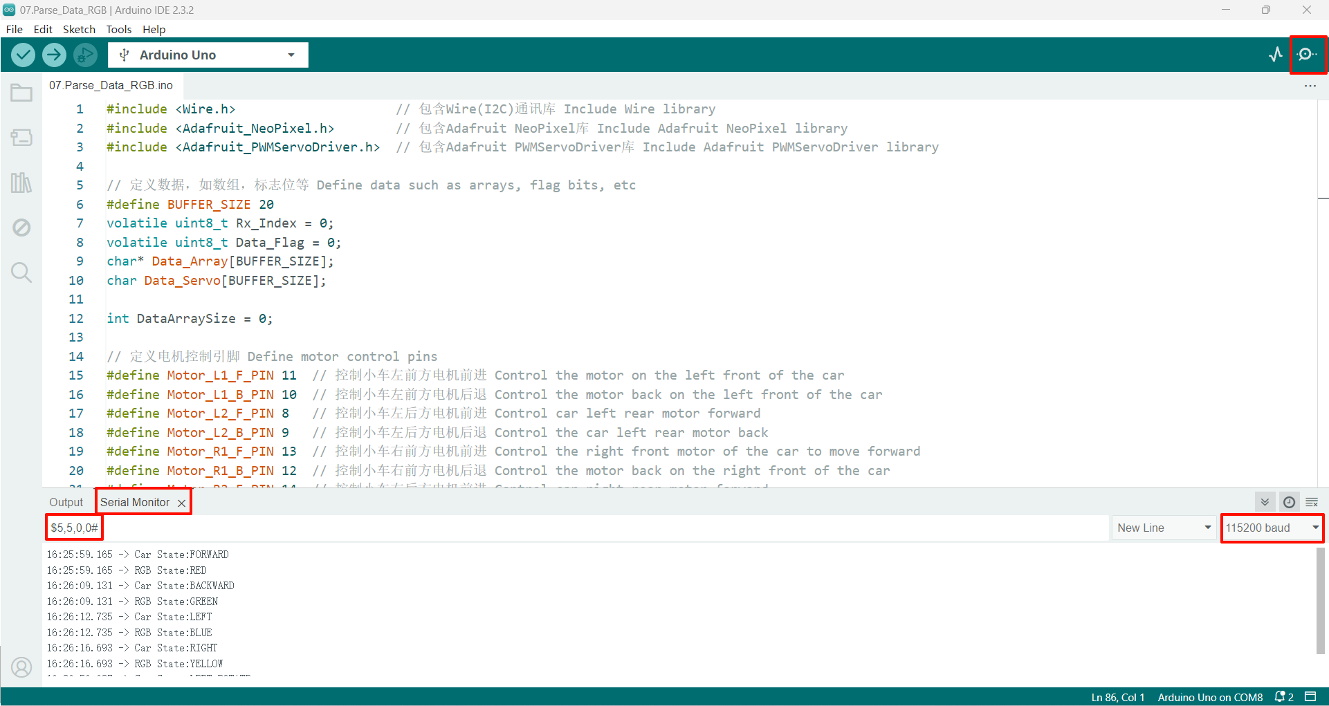
After compiling the program successfully, upload the code to the Arduino Uno development board.
After the program is started, send data in the specified format. The program will set the car and RGB status according to the first and second bits of the data, and the serial port will return the parsed data!
If there is no display content, you can check whether the serial port baud rate is consistent with the code setting, and then press the RESET button on the development board.
xxxxxxxxxxThe drive motor needs an external battery pack and the expansion board switch is turned on to drive normally.The burning program cannot use other programs to occupy the serial port or an external serial communication module (for example: WiFi camera module), otherwise the program cannot be burned or an error message will be prompted!