Welcome to Roboduino V2 repository
7. Face following
Face following
Face followingDevice connectionHardware connectionSoftware connectionImplementation ideasCode analysisExperimental resultsAPP connectionEffectNotes
We can view the WiFi camera screen through the APP. When a face is detected, the servo rotates with the face.
xxxxxxxxxxSince the previous tutorial has explained the basic knowledge of all car modules, the car control tutorial will not be repeated. The main focus is on the implementation ideas of the car functions!
Device connection
Hardware connection
Use Type-B data cable to connect Arduino Uno and computer.
Before this, you need to unplug the connection between the WiFi camera and Roboduino, otherwise the serial port will be occupied and the computer cannot recognize the serial port number of Arduino Uno.
Software connection
Open the "Arduino IDE" software and select the model and serial port number corresponding to the development board.
Implementation ideas
Analyze the data sent by the WiFi camera through the serial port and control the car according to the data.
Code analysis
Here is only a brief introduction to the code content. For detailed code, it is recommended to refer to the corresponding code file, which is provided in the download area!
- esp32_wifi
- Define a macro
WIFI_MODEto select different WiFi modes based on preprocessor directives (#if)
xxxxxxxxxx#if MODE_AP_STA#define WIFI_MODE '2'#elif MODE_STA#define WIFI_MODE '1'#elif MODE_AP#define WIFI_MODE '0'#else#define WIFI_MODE '2'#endif
- Enumerate AI modes, including cat and dog detection, face detection, color detection, etc.
xxxxxxxxxxtypedef enum AI_mode_t{Nornal_AI = 0, //不检测 No detectionCat_Dog_AI, //猫狗检测 Cat and Dog DetectionFACE_AI, //人物检测 People DetectionCOLOR_AI , //颜色识别 Color recognitionREFACE_AI, //人脸识别 Face RecognitionQR_AI = 5, //二维码识别 QR code recognitionAI_MAX //最大值 Maximum}AI_mode;
SET_ESP_WIFI_MODEfunction sets the WiFi mode of the ESP32 camera.
xxxxxxxxxxvoid SET_ESP_WIFI_MODE(void) //设置模式选择 Setting Mode Selection{//选择模式STA+AP模式共存 Select mode STA+AP mode coexistencesprintf(send_buf,"wifi_mode:%c",WIFI_MODE);ESPWIFISerial.print(send_buf);memset(send_buf,0,sizeof(send_buf));delay(2000);//等待复位重启成功 Wait for reset to restart successfully}
- The
SET_ESP_AI_MODEfunction sets the AI mode of the ESP32 camera.
xxxxxxxxxxvoid SET_ESP_AI_MODE(AI_mode Mode) //设置AI模式 Setting AI Mode{sprintf(send_buf,"ai_mode:%d",Mode);ESPWIFISerial.print(send_buf);memset(send_buf,0,sizeof(send_buf));runmode = Mode;delay(2000);//等待复位重启成功 Wait for reset to restart successfully}
- bsp_servo
- Contains
Wire,Adafruit_PWMServoDriverlibraries
xxxxxxxxxx#include <Wire.h> // Include Wire (I2C) communication library Include Wire library#include <Adafruit_PWMServoDriver.h> // Include Adafruit PWMServoDriver library Include Adafruit PWMServoDriver library
- Define the servo-related parameters, control pins and the underlying chip I2C address
xxxxxxxxxx// 定义舵机相关参数 Define servo related parameters#define SERVO_MIN_PULSE_WIDTH 500#define SERVO_MAX_PULSE_WIDTH 2500#define SERVO_PULSE_WIDTH_CYCLE 20000#define SERVO_MIN_ANGLE 0#define SERVO_MAX_ANGLE 180#define PWM_FREQUENCY 50// 定义舵机控制引脚 Define the servos control pin#define Servo1_PIN 0#define Servo2_PIN 1#define Servo3_PIN 2#define Servo4_PIN 3// 定义底层芯片I2C设备地址 Define the IIC address of the Bottom-layer driver chip#define Bottom_Layer_Driver_ADDR 0x40
- Limit the servo angle range
xxxxxxxxxx//Servo Angle Limiter#define MinAngle (35)#define MaxAngle (145)
- Create an instance of
Adafruit_PWMServoDriver
xxxxxxxxxx// 创建Adafruit_PWMServoDriver类的实例 Create an instance of the Adafruit_PWMServoDriver classAdafruit_PWMServoDriver pwmservo = Adafruit_PWMServoDriver(Bottom_Layer_Driver_ADDR);
- Servo control initialization
xxxxxxxxxx//Servo initializationvoid servo_init(void){Wire.begin(); // 初始化I2C通讯 Initialize I2C communicationdelay(1000); // 如果控制异常,可以适当增加延时 If the function is abnormal, you can increase the delaypwmservo.begin(); // PWM初始化 Initialize the Pulse Width Modulation (PWM) librarypwmservo.setPWMFreq(PWM_FREQUENCY); // 设置PWM频率 Set the PWM frequency}
- Set the servo rotation
xxxxxxxxxx/*** @brief 设置舵机旋转角度 Set the servo rotation angle* @param servoPin: 舵机控制引脚 Servo control pin* @param angle: 舵机旋转角度 Servo rotation angle* @retval 无 None*/void setServoAngle(uint8_t servoPin, int angle){long pulseWidth = map(angle, SERVO_MIN_ANGLE, SERVO_MAX_ANGLE, SERVO_MIN_PULSE_WIDTH, SERVO_MAX_PULSE_WIDTH);long PWM_Value = pulseWidth * 4096 / SERVO_PULSE_WIDTH_CYCLE;pwmservo.setPWM(servoPin, 0, PWM_Value);}
- The
limit_servofunction limits the angle of the servo to ensure that the angle value is between the predefined minimum value MinAngle and the maximum value MaxAngle.
xxxxxxxxxxint limit_servo(int angle){if(angle <= MinAngle){return MinAngle;}else if(angle>=MaxAngle){return MaxAngle;}return angle;}
- follow_pid
- The gain parameters for servo PID control are defined, and floating-point and integer variables are declared to store the variables required for these servo PID control.
xxxxxxxxxx#define KP_servo (0.07) //0.03#define KI_servo (0.0001) //#define KD_servo (0.002) //0.001float KP_S,KI_S,KD_S; //舵机PID Servo PIDint error_servo,error_last_servo,error_last_last_servo;
- Define the
myabsfunction to calculate the absolute value of an integer.
xxxxxxxxxxint myabs(int a){if(a<0)return -a;return a;}
- Define the
init_servo_PIDfunction to initialize the parameters of the servo PID controller.
xxxxxxxxxxvoid init_servo_PID(void){KP_S = KP_servo;KI_S = KP_servo;KD_S = KD_servo;error_servo = 0;error_last_servo = 0;error_last_last_servo = 0;esp32_ai_msg.cx = 160;}
- Define the
PID_count_servofunction to calculate the output of the servo PID controller, that is, the adjustment amount of the servo angle.
xxxxxxxxxxfloat PID_count_servo(void){static float pwmservo = 0;error_servo = 160 - esp32_ai_msg.cx;//增量式 Incrementalpwmservo = pwmservo + (error_servo-error_last_servo) *KP_S +error_servo * KI_S +(error_servo - 2*error_last_servo +error_last_last_servo) *KD_S;error_last_servo = error_servo;error_last_last_servo = error_last_servo;if(pwmservo <-90) pwmservo = -90;else if(pwmservo>90) pwmservo = 90;// char temp[50]={'\0'};// sprintf(temp,"%d,\r\n",(int)pwmservo);// ESPWIFISerial.println(temp);return pwmservo;}
- Define the
Car_Follow_Startfunction to start the servo following function, obtain the servo angle adjustment amount by calling the PID calculation function, and set the servo angle.
xxxxxxxxxxvoid Car_Follow_Start(void){int PWM_angle;PWM_angle =(int)PID_count_servo();PWM_angle = limit_servo(90+PWM_angle);//驱动舵机位置 Driving servo positionsetServoAngle(Servo1_PIN, PWM_angle);}
- face_follow_servo
- Import header files, including the implementation of ESP32's WiFi function, motor control, servo control, PID control, button management, and RGB light control.
xxxxxxxxxx#include <stdio.h>#include "esp32_wifi.hpp"#include "motor_car.hpp"#include "esp_key.hpp"#include "bsp_RGB.hpp"#include "bsp_servo.hpp"#include "follow_pid.hpp"
A macro
AI_set_modeis defined here, indicating that the current AI mode isFACE_AI(face detection).cmd_flagis an external variable used to indicate the current command status.
xxxxxxxxxx#define AI_set_mode FACE_AI //Setting AI Mode#define BUZZER_PIN 10extern uint8_t cmd_flag;
mode_chage()is a mode switching function that sets the value ofcmd_flagaccording to the current operating mode to indicate different processing modes.
xxxxxxxxxxvoid mode_chage(){if(runmode == Nornal_AI){cmd_flag = 2;//进入透传模式 Enter transparent mode}else if(runmode == REFACE_AI ){cmd_flag = 3;//解析人脸识别数据 Parsing facial recognition data}else if(runmode == QR_AI ){cmd_flag = 4;//解析二维码数据 Parsing QR code data}else{cmd_flag = 5;//其它AI模式数据 Other AI mode data}}
- The
setup()function is the entry point for the initialization program, including the initialization of the servo, buzzer, button, serial port, WiFi, AI mode, motor and RGB light, and calls themode_chagefunction to set the command flag and set the initial angle of the servo to 90°.
xxxxxxxxxxvoid setup(){//Servo pid initializationinit_servo_PID();pinMode(BUZZER_PIN, OUTPUT); //蜂鸣器初始化 Buzzer initializationinit_key();//按键初始化 Button initializationserial_init();//串口初始化 Serial port initializationSET_ESP_WIFI_MODE();//设置wifi模式 Set Wi-Fi modeSET_ESP_AI_MODE(AI_set_mode);//设置AI模式 Setting AI ModeMotor_init();//电机初始化 Motor initializationservo_init();//舵机初始化 Servo initializationRGB_init();//RGB初始化 RGB initializationmode_chage();//根据模式选择解析数据办法 Choose the method to parse data according to the mode//setCarMove(FORWARD,35); //35-255setServoAngle(Servo1_PIN, 90);}
- In the main loop, when the operation mode is color recognition or face recognition, the state detection of the virtual button is called. If new data is received, newlines is reset to 0, and the
Car_Follow_Start()function is called to control the speed of the car.
xxxxxxxxxxvoid loop(){//Key logo and RGB light color Only these two modes will use key interactionif(runmode == COLOR_AI || runmode==REFACE_AI ){key_goto_state();//虚拟按键 Virtual buttons}if(newlines == 1)//接收到新数据 New data received{newlines = 0;//PID计算 PID calculationCar_Follow_Start();}}
Experimental results
After compiling the program successfully, upload the code to the Arduino Uno development board, disconnect the car from the computer, and connect the WiFi camera to the serial port on the expansion board.
After the program starts, we can observe the camera screen through the YahboomCAM APP.
APP connection
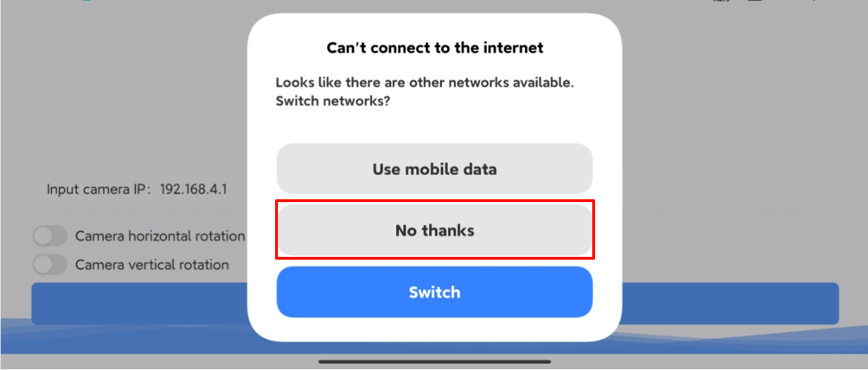
Connect the mobile phone to the hotspot of the WiFi camera (the name of the built-in hotspot: Yahboom_ESP32_WIFI), and then open the YahboomCam software.
xxxxxxxxxxSome mobile phones will prompt for connecting to a hotspot without a network, and we need to click to keep connected!
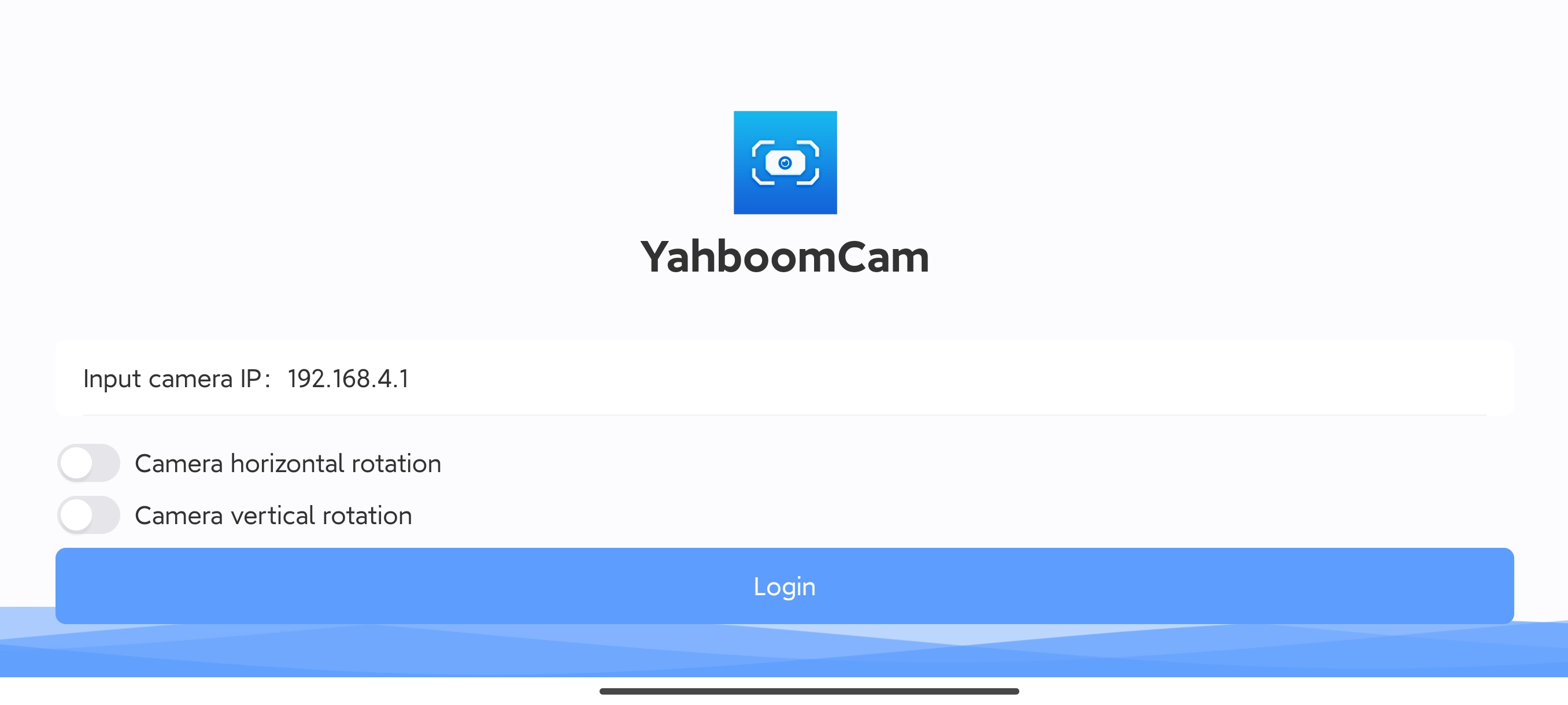
Enter IP:192.168.4.1 in the YahboomCam software, then click Login to enter the APP control interface.
xxxxxxxxxxThe IP of the WiFi camera's built-in hotspot is 192.168.4.1
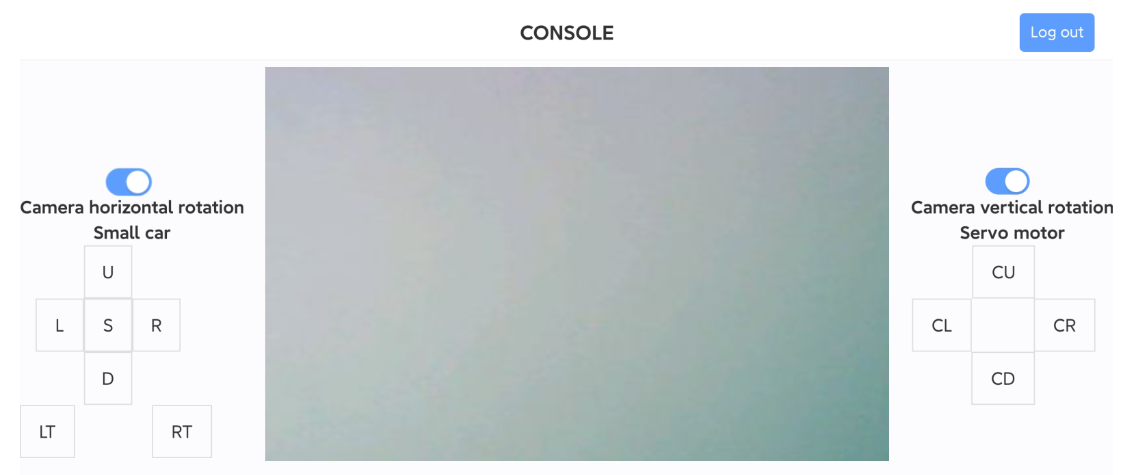
After entering the APP interface, the APP will display the camera screen.
xxxxxxxxxxIf there is no screen, check whether the phone is connected to the WiFi camera hotspot normally
Effect
When a face is detected, the servo rotates with the face.
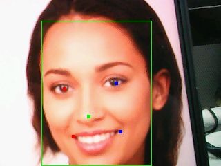
Face:

Notes
- The screen needs to be turned on to start recognition. If the screen is turned off, the recognition will also be turned off.
- Make sure the direction of the camera screen is correct. You need to turn on the vertical rotation and horizontal rotation switches on the APP, otherwise the following direction will be opposite.