Welcome to K210 Module repository
2.MSPM0-Color follow
MSPM0 color follower
MSPM0 color follower1. Opening instructions2. Experimental preparationThe relationship between the 4 motor interfaces and the car is as follows:Hardware wiringWiring using MSPM0 robot expansion boardWiring using MSPM0G3507 core board (Yahboom)Wiring pins3. Key code analysis4. Experimental operation5. Experimental phenomenon
1. Opening instructions
Please read the "Motor Introduction and Usage" in the four-way motor driver board information first to understand the motor parameters, wiring method, and power supply voltage you are currently using. To avoid burning the motherboard or motor.
Motor: The case and code take the 520L motor of our store as an example.
2. Experimental preparation
National race chassis V2 four-wheel drive version, 4*L520 motor, 12V lithium battery, K210 vision module, MSPM0 robot expansion board (optional), MSPM0G3507 core board (Yahboom).
The relationship between the 4 motor interfaces and the car is as follows:
M1 -> upper left motor (left front wheel of the car)
M2 -> lower left motor (left rear wheel of the car)
M3 -> upper right motor (right front wheel of the car)
M4 -> lower right motor (right rear wheel of the car)
Hardware wiring
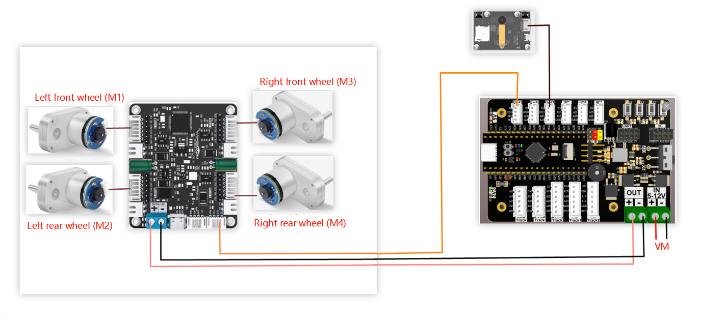
Wiring using MSPM0 robot expansion board
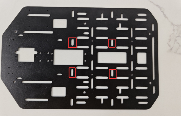
During the installation and wiring process, if the wiring length is not enough, you can move the MSPM0 robot expansion board forward a little and install it, as shown in the following figure.
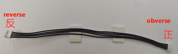
Note: The wire used for the k210 vision module and the wire used to connect the MSPM0 robot expansion board and the four-way motor driver module are: PH2.0-4pin cable, double-ended all black, reverse (200mm), the direction of the reverse cable holder is shown in the following figure
Wiring using MSPM0G3507 core board (Yahboom)
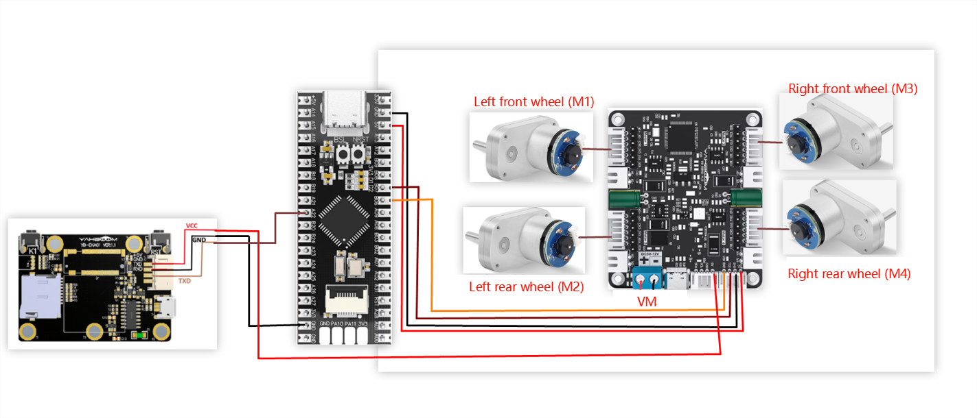
Wiring pins
| Four-way motor driver board | MSPM0G3507 core board (Yahboom) |
|---|---|
| RX2 | PB6 |
| TX2 | PB7 |
| GND | GND |
| 5V | 5V |
Take M1 motor as an example below, and other motors are similar
| Motor | Four-way motor driver board (Motor) |
|---|---|
| M+ | M1+ |
| M- | M1- |
| GND | GND |
| VCC | 3V3 |
| B | H1A |
| A | H1B |
| K210 vision module | MSPM0G3507 core board (Yahboom) |
|---|---|
| 5V | 5V |
| GND | GND |
| TXD | PA22 |
| RXD | PA21 |
3. Key code analysis
- revaction.c
x// 获取命令标志 Get command flaguint8_t Get_CMD_Flag(void){ return New_CMD_flag;}// 清除命令数据和相关标志 Clear command data and related flagsvoid Clear_CMD_Flag(void){ for (uint8_t i = 0; i < New_CMD_length; i++) { RxBuffer[i] = 0; } New_CMD_length = 0; New_CMD_flag = 0;}//数据分析 data analysisvoid Upper_Data_Parse(uint8_t *data_buf, uint8_t num){ uint8_t func_id = *(data_buf + 3); switch (func_id) { /* 判断功能字:小车速度设置 Judgment function word: Trolley speed setting */ case FUNC_MOTION: { uint8_t parm = (uint8_t) *(data_buf + 4); int16_t Vx_recv = *(data_buf + 6) << 8 | *(data_buf + 5); int16_t Vy_recv = *(data_buf + 8) << 8 | *(data_buf + 7); int16_t Vz_recv = *(data_buf + 10) << 8 | *(data_buf + 9); uint8_t adjust = parm & 0x80; if (Vx_recv == 0 && Vy_recv == 0 && Vz_recv == 0) { Contrl_Pwm(0,0,0,0); } else { Motion_Car_Control(Vx_recv, Vy_recv, Vz_recv, (adjust==0?0:1)); } break; } /* 判断功能字:彩灯控制 Judgment function word: color light control */ case FUNC_RGB: { u8 index = *(data_buf + 4); u8 red = *(data_buf + 5); u8 green = *(data_buf + 6); u8 blue = *(data_buf + 7);// printf("RED:%d, G:%d, B:%d\r\n",red,green,blue); RGB_Set_Color(index, red, green, blue); RGB_Update(); break; } default: break; }}//数据接收并保存 Data received and savedvoid Upper_Data_Receive(uint8_t Rx_Temp){ switch (RxFlag) { case 0: if (Rx_Temp == PTO_HEAD) { RxBuffer[0] = PTO_HEAD; RxFlag = 1; } break; case 1: if (Rx_Temp == PTO_DEVICE_ID) { RxBuffer[1] = PTO_DEVICE_ID; RxFlag = 2; RxIndex = 2; } else { RxFlag = 0; RxBuffer[0] = 0x0; } break; case 2: New_CMD_length = Rx_Temp + 2; if (New_CMD_length >= PTO_MAX_BUF_LEN) { RxIndex = 0; RxFlag = 0; RxBuffer[0] = 0; RxBuffer[1] = 0; New_CMD_length = 0; break; } RxBuffer[RxIndex] = Rx_Temp; RxIndex++; RxFlag = 3; break; case 3: RxBuffer[RxIndex] = Rx_Temp; RxIndex++; if (RxIndex >= New_CMD_length) { New_CMD_flag = 1; RxIndex = 0; RxFlag = 0; } break; default: break; }}Get_CMD_Flag: Get the k210 data flag
Clear_CMD_Flag: Clear command data and related flags
Upper_Data_Parse: Parse the saved k210 data and determine the function of k210
Upper_Data_Receive: Save the received k210 data
- app_motor.c
xxxxxxxxxx// 返回当前小车轮子轴间距和的一半 Returns half of the sum of the axle spacings of the current trolley wheels.static float Motion_Get_APB(void){ return Car_APB;}void Set_Motor(int MOTOR_TYPE){ if(MOTOR_TYPE == 1) { send_motor_type(1);//配置电机类型 Configure motor type delay_ms(100); send_pulse_phase(30);//配置减速比 查电机手册得出 Configure the reduction ratio. Check the motor manual to find out delay_ms(100); send_pulse_line(11);//配置磁环线 查电机手册得出 Configure the magnetic ring wire. Check the motor manual to get the result. delay_ms(100); send_wheel_diameter(67.00);//配置轮子直径,测量得出 Configure the wheel diameter and measure it delay_ms(100); send_motor_deadzone(1900);//配置电机死区,实验得出 Configure the motor dead zone, and the experiment shows delay_ms(100); } ... else if(MOTOR_TYPE == 5) { send_motor_type(1); delay_ms(100); send_pulse_phase(40); delay_ms(100); send_pulse_line(11); delay_ms(100); send_wheel_diameter(67.00); delay_ms(100); send_motor_deadzone(1900); delay_ms(100); }}void Motion_Car_Control(int16_t V_x, int16_t V_y, int16_t V_z, uint8_t adjust){ float robot_APB = Motion_Get_APB(); speed_lr = 0; speed_fb = V_x; speed_spin = (V_z / 1000.0f) * robot_APB; if (V_x == 0 && V_y == 0 && V_z == 0) { Contrl_Speed(0,0,0,0); return; } speed_L1_setup = speed_fb - speed_spin; speed_L2_setup = speed_fb - speed_spin; speed_R1_setup = speed_fb + speed_spin; speed_R2_setup = speed_fb + speed_spin; if (speed_L1_setup > 1000) speed_L1_setup = 1000; if (speed_L1_setup < -1000) speed_L1_setup = -1000; if (speed_L2_setup > 1000) speed_L2_setup = 1000; if (speed_L2_setup < -1000) speed_L2_setup = -1000; if (speed_R1_setup > 1000) speed_R1_setup = 1000; if (speed_R1_setup < -1000) speed_R1_setup = -1000; if (speed_R2_setup > 1000) speed_R2_setup = 1000; if (speed_R2_setup < -1000) speed_R2_setup = -1000; // printf("%d\t,%d\t,%d\t,%d\r\n",speed_L1_setup,speed_L2_setup,speed_R1_setup,speed_R2_setup); Contrl_Speed(speed_L1_setup, speed_L2_setup, speed_R1_setup, speed_R2_setup); }Motion_Get_APB: Returns half of the current wheel axle spacing of the car
Set_Motor: Sets the motor type of the four-way motor driver board, and changes the motor type according to your actual situation
Motion_Car_Control: Controls the different motion states of the car
- app_motor_usart.c
xxxxxxxxxx//发送电机类型 Transmitter motor typevoid send_motor_type(motor_type_t data){ sprintf((char*)send_buff,"$mtype:%d#",data); Send_Motor_ArrayU8(send_buff, strlen((char*)send_buff)); }//发送电机死区 Send motor dead zonevoid send_motor_deadzone(uint16_t data){ sprintf((char*)send_buff,"$deadzone:%d#",data); Send_Motor_ArrayU8(send_buff, strlen((char*)send_buff));}//发送电机磁环脉冲 Send motor magnetic ring pulsevoid send_pulse_line(uint16_t data){ sprintf((char*)send_buff,"$mline:%d#",data); Send_Motor_ArrayU8(send_buff, strlen((char*)send_buff));}//发送电机减速比 Transmitting motor reduction ratiovoid send_pulse_phase(uint16_t data){ sprintf((char*)send_buff,"$mphase:%d#",data); Send_Motor_ArrayU8(send_buff, strlen((char*)send_buff));}//发送轮子直径 Send wheel diametervoid send_wheel_diameter(float data){