yahboom
HomeLearn
Solution
Blog
Online Store
About Us
EN/中文
K210 Module📖
0.Camera changes
  • Precautions for camera changes
1.K210-AI-Camera introduction
  • 1.K210 main chip introduction
  • 2.K210 visual recognition module introduction
  • 3.Module pin assignments
  • 4.MicroPython Introduction
  • 5. FAQ analysis
  • 6.Bracket installation
2.Development Environment Setup
  • 1.To install the serial port assistant
  • 2.Install CanMV IDE development software
  • 3.Flashcard factory firmware
  • 4.IDE import routine
  • 5.Call custom py library
  • 6.MicroPython API documentation
3.Basic experimental routines
  • 1.Lighting the RGB light experiment
  • 2.Key features of the experiment
  • 3.Timer experiment
  • 4.PWM breathing light experiment
  • 5.LCD display experiment
  • 6.The touchpad read the coordinates of the experiment
  • 7.The camera shows the experimental
  • 8.Memory card read and write files of the experiment
  • 9.External interface experimental
4.Graphical manipulation routines
  • 1.Draw graphics
  • 2.Button and the click event
  • 3.Slider
  • 4.Chart animation
  • 5.Multi-label layout
5.AI visual experiments routines
  • How to import the model file into memory cardnew
  • 1.Color recognition
  • 2.Barcode recognition
  • 3.QR code recognition
  • 4.Apriltags recognition
  • 5.Face detection
  • 6.Face feature detection
  • 7.Mask detection
  • 8.Face recognition
  • 9.Object detection
  • 10.Self-learning classification
  • 11.Handwritten digit recognition
  • 12. Multiple color recognition
  • 13. Human body detectionnew
  • 14. Yolo hand detectionnew
  • 15. License Plate Recognitionnew
  • 16. Autonomous training modelnew
6.Extended routines (sold separately)
6.1.For STM32 Car
  • 10. stm_ K210 Autonomous Learning Classification
  • 1.automatic driving
  • 2.color follow
  • 3.Handwriting digital operation
  • 4.Color reaction
  • 5.Road sign indicating the operation
  • 6.Following the apriltag
  • 7.QR code instruction
  • 8.PTZ tracking color
  • 9.PTZ tracking face
6.2.1 arduino_k210
  • 1.ard_k210-Color recognition
  • 2.ard_k210-Bar code identification
  • 3.ard_k210-QR code identification
  • 4.ard_ K210-mechanical code identification
  • 5.ard_ K210-Face Detection
  • 6. ard_ K210-facial feature detection
  • 7. ard_ K210-mask detection
  • 8. ard_ K210-facial recognition
  • 9. ard_ K210-object detection
  • 10. ard_ K210 Autonomous Learning Classification
  • 11. ard_ K210 Handwritten Digit Recognition
6.2 K210 as a coprocessor
  • ReadMe
6.2.2 stm32_k210
  • 1.stm_ K210 color recognition
  • 2. stm_ K210 barcode recognition
  • 3. stm_ K210 QR code recognition
  • 4. stm_ K210 mechanical code identification
  • 5. stm_ K210 Face Detection
  • 6.stm_ K210 facial feature detection
  • 7. stm_ K210 mask detection
  • 8. stm_ K210 facial recognition
  • 9. stm_ K210 object detection
  • 11. stm_ K210 Handwritten Digit Recognition
6.2.3 microbit_k210
  • 1.microbit_ K210 color recognition
  • 2.microbit_ K210 barcode recognition
  • 3.microbit_ K210 QR code recognition
  • 4.microbit_ K210 mechanical code identification
  • 5. microbit_ K210 Face Detection
  • 6. microbit_ K210 facial feature detection
  • 7. microbit_ K210 mask detection
  • 8. microbit_ K210 facial recognition
  • 9. microbit_ K210 object detection
  • 10. microbit_ K210 autonomous classification learning
  • 11. microbit_ K210 Handwritten Digit Recognition
6.2.4 pico_k210
  • 1. pico_ K210 color recognition
  • 2. Pico_ K210 barcode recognition
  • 3. Pico_ K210 QR code recognition
  • 4. pico_ K210 machine code recognition
  • 5. pico_ K210 Face Detection
  • 6. pico_ K210 facial feature detection
  • 7. pico_ K210 mask recognition
  • 8. pico_ K210 facial recognition
  • 9. pico_ K210 object detection
  • 10. pico_ K210 Autonomous Learning Classification
  • 11. pico_ K210 Handwritten Digit Recognition
6.2.5 MSPM0G3507_k210
  • 1.MSPM0_K210 color recognition
  • 2.MSPM0_K210 barcode recognition
  • 3.MSPM0_K210 QR code recognition
  • 4.MSPM0_K210 mechanical code recognition
  • 5.MSPM0_K210 face detection
  • 6.MSPM0_K210 facial feature detection
  • 7.MSPM0_K210 mask detection
  • 8.MSPM0_K210 face recognition
  • 9.MSPM0_K210 Object Detection
  • 10.MSPM0_K210 Self-study classification
  • 11.MSPM0_K210 handwritten digit recognition
6.2.6 MSPM0G3519_k210
  • 1. MSPM0_K210 Color Recognitionnew
  • 2. MSPM0_K210 Barcode Recognitionnew
  • 3. MSPM0_K210 QR Code Recognitionnew
  • 4. MSPM0_K210 Mechanical Code Recognitionnew
  • 5. MSPM0_K210 Face Detectionnew
  • 6. MSPM0_K210 Facial Feature Detectionnew
  • 7. MSPM0_K210 Mask Detectionnew
  • 8. MSPM0_K210 Face Recognitionnew
  • 9. MSPM0_K210 Object Detectionnew
  • 10. MSPM0_K210 Self-study Classificationnew
  • 11. MSPM0_K210 Handwritten Digit Recognitionnew
6.3 For 24 channel servo drive board
  • 1. 2DOF PTZ Color Tracking
  • 2. 2DOF Face Tracking
  • 3. 2DOF Fruit sorting
6.4 For autopilot map
  • 1.k210 model training
  • 2.Assembly and wiring of stm32 car
  • 3.Recognize left and right sign
  • 4.Identify and remove speed limit
  • 5.Identify parking spaces and park
  • 6.STM32 car autopilot
6.5.1 For MSPM0G3507_Wheeled Chassis Kit
  • 1.MSPM0-Automatic Driving
  • 2.MSPM0-Color follow
  • 3.MSPM0-Number recognition
  • 4.MSPM0-Color reaction
  • 5.MSPM0-Road signs
  • 6.MSPM0-Machine code following
  • 7.MSPM0-QR code recognition
6.5.2 For MSPM0G3519_Wheeled Chassis Kit
  • 1.MSPM0-Automatic Drivingnew
  • 2.MSPM0-Color follownew
  • 3.MSPM0-Number recognitionnew
  • 4.MSPM0-Color reactionnew
  • 5.MSPM0-Road signsnew
  • 6.MSPM0-Machine code followingnew
  • 7.MSPM0-QR code recognitionnew
6.5.3 For STM32_Wheeled Chassis Kit
  • 1.STM32-Automatic Driving
  • 2.STM32-Color follow
  • 3.STM32-Number recognition
  • 4.STM32-K210-Color Reaction
  • 5.STM32-Road signs
  • 6.STM32-Machine code following
  • 7.STM32-QR code recognition
Download
  • Driver development software
  • AI model
  • Source code
  • Instruction manual
  • Hardware_3DModelFile
  • K210_Chip_Data
Download ZIP

Welcome to K210 Module repository

6.STM32 car autopilot

STM32 car autopilot

STM32 car autopilot1.Experiment preparation2.Car wiring2.1 Stm32 and dual driver board wiring part2.2 Wiring of STM32F103RCT6 and infrared sensor2.3 Wiring of STM32RCT6 and k2103.Main source code analysis4.Experimental results5.Notes about this routine

1.Experiment preparation

  1. knowledge reserve
  • Have good programming ability (mainly C language)
  • Familiar with the architecture of stm32
  1. Material preparation
  • Smart car mini chassis *1
  • stm32F103RCT6 *1
  • Yahboom's dual motor driver board *2 (Other motor driver boards may not be suitable for the source code provided in this tutorial, you need to transplant it yourself)
  • Four-way tracking module *1
  • 310 motor*4
  • k210 viewing angle module *1
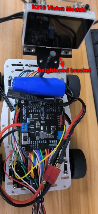
  • K210 angle of view module heightened bracket *1
  • 7.4V battery *1
  • Several DuPont lines
  • M3 copper pillars, several M3 screws
  1. k210 viewing angle module preparation 3.1 Take the TF card out of the k210 vision module and insert it into the card reader.
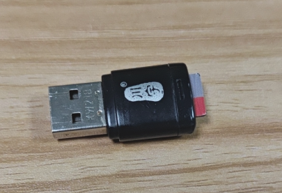
01

3.2 Insert the card reader into the computer and wait for the computer to recognize the U disk
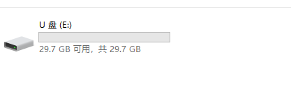
02

3.3 After the computer recognizes it, enter it into the TF card.

03

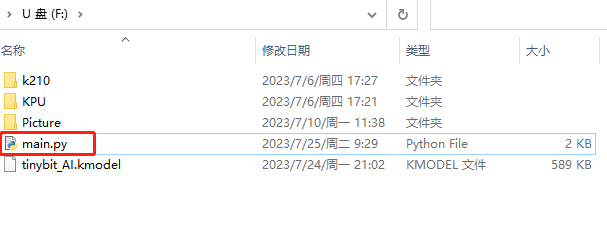
3.4 Find the k210 folder in the source code of the data program, find the 20_tinybit_AI_sport.py and tinybit_AI.kmodel files from the folder, and copy them to the root directory.

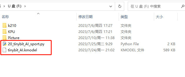
04

05

3.5 Delete the main file and rename the 20_tinybit_AI_sport.py file to the main file.
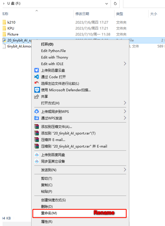
06

07

3.6 After renaming, pull out the card reader, take out the TF card, and insert it back into the k210 vision module.

2.Car wiring

After the car is assembled, as shown in the figure below
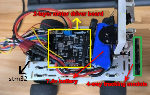
08

09

2.1 Stm32 and dual driver board wiring part

  1. Wiring of stm32F103RCT6 and dual motor board (top board)
STM32RCT6The top 2-channel motor board
PA11BN1
PA8BN2
PC6AN1
PC7AN2
3.33V3
GNDGND
PA0E2A
PA1E2B
PA15E1A
PB3E1B
  1. Wiring of stm32F103RCT6 and dual motor board (lowest board)
STM32RCT6The bottom 2-channel motor board
PB0BN1
PB1BN2
PC8AN1
PC9AN2
3.33V3
GNDGND
PA7E2A
PA6E2B
PB7E1A
PB6E1B
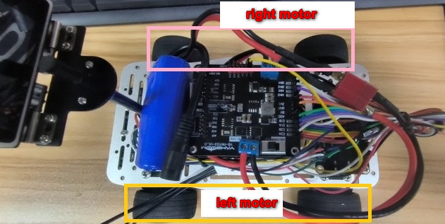
  1. The motor drive board on the top layer is the motor of the two wheels (that is, the front motor) that is connected to the electromagnetic sensor,

    motorA--->right motor、motorB--->left motor

  2. The motor drive board at the bottom is connected to the two-wheeled motors away from the electromagnetic sensor (that is, the motor at the back),

motorA--->right motor、motorB--->left motor
10

2.2 Wiring of STM32F103RCT6 and infrared sensor

STM32RCT64-way line inspection sensor
PA5S1
PA4S2
PA3S3
PA2S4
3.3VVCC
GNDGND

2.3 Wiring of STM32RCT6 and k210

STM32RCT6k210
PA9RXD
PA10TXD
VCCVCC
GNDGND


3.Main source code analysis

int main(void)
{
    //A series of initialization work...
    while(1)
    {
        switch(id_num_back)
        {
            case red_light: 
                Motion_Set_Pwm(0,0,0,0);//car stop
                set_dataid(MAX_id);//back to normal patrol
            break;
            
            case green_light:
                set_dataid(MAX_id);//back to normal patrol
            break;
            
            case school:
            case walk:
                set_dataid(MAX_id);//back to normal patrol
                break;
        
            case right:
                Road_sign_right();//Right turn priority line patrol
            break;
            
            case left:
                Road_sign_left();//Left turn priority line patrol
                break;
            
            case freeSpeed:
                set_dataid(MAX_id);//back to normal patrol
                break;
            
            case limitSpeed:
                Road_sign_speedlimit();//low speed line patrol
            break;
            
            case chuku_track_line://Line patrol after leaving the warehouse
                    car_outbound_track();
                    break;
            
            case one:
            case two:
            case horn:
                break;
            
            default: Track_line();//Call the normal line following function
        }
    }
    //...
}
  • After booting, stm32 waits for 7 seconds to wait for the k210 module to enter the working state normally
  • Track_line: This function is a normal line patrol movement. If no road signs are recognized, this function is usually called for movement.
  • Reverse_parking_no1: This is the process of driving the car back to No. 1 parking garage when k210 recognizes the number 1
  • Car_outbound : This is to successfully drive into the No. 1 parking garage, stop for 2 seconds, then drive out of the garage, and then perform line inspection after exiting the garage
  • Road_sign_left: After k210 recognizes the road sign for turning left, it will perform the processing of line inspection for turning left
  • Reverse_parking_no2: This is when the k210 recognizes the number 2, the process of driving the car back into the No. 2 garage
  • Car_outbound_track: This is the processing of line inspection after leaving the garage, and it will return to normal line inspection after a period of time.
  • Road_sign_right: After the k210 recognizes the right-turn road sign, it will perform the processing of right-turn priority line inspection
  • Road_sign_speedlimit: Recognize the speed limit sign, drive the car into the speed limit movement
  • set_dataid: This function is to directly set the state of the car.

The flow chart of the program is roughly as follows 17
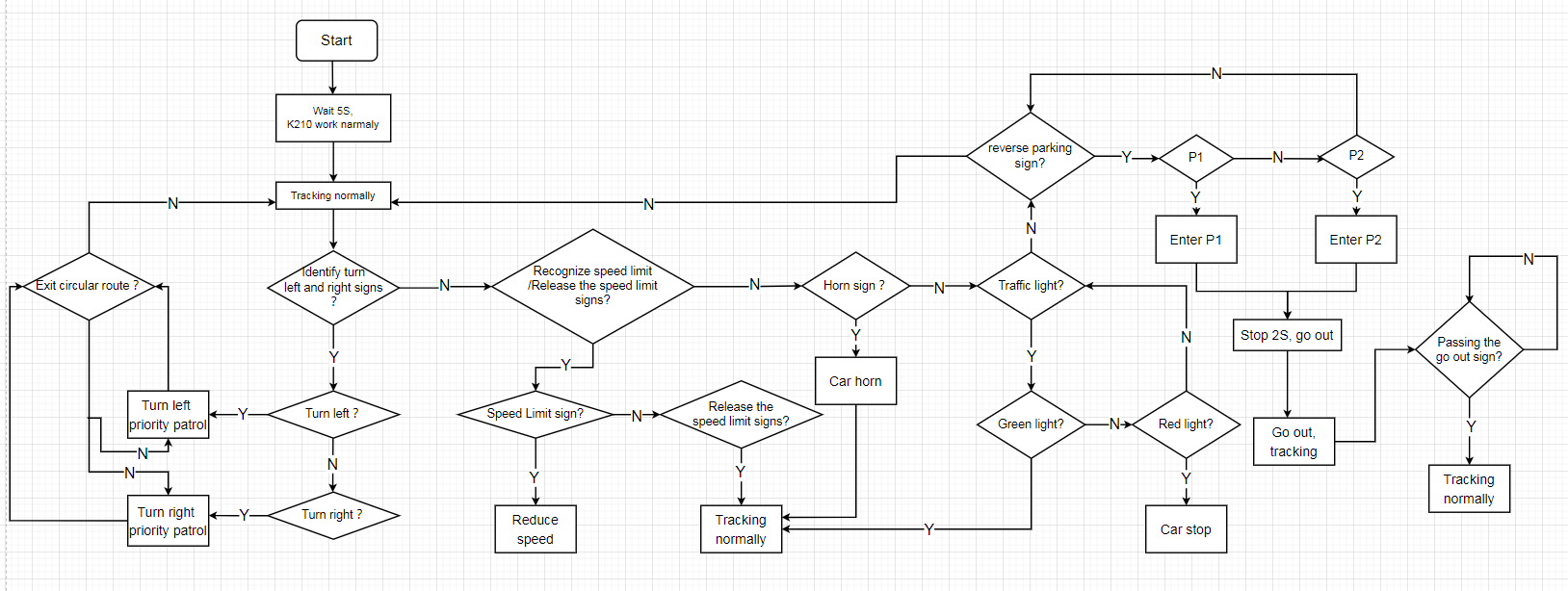
The source code provided in this tutorial retains the RGB\LCD\IMU\external Flash driver on the STM32F103RCT6 board, which can be called directly to facilitate secondary development

4.Experimental results

After everything is normal, the car will start along the map and plan the path of the tracking movement. When the road sign is recognized, the corresponding path planning movement will appear.

  1. When the speed limit sign is recognized, the car will do a speed patrol movement that does not exceed the speed limit sign
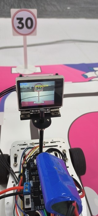
25

  1. When the speed limit sign is recognized, the car will return to the normal line patrol movement.
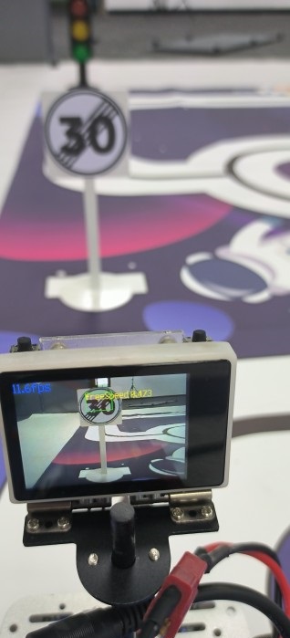
19

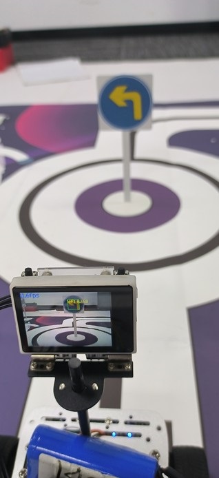
  1. When a left/right turn is recognized, the car will make a priority left/right turn patrol movement
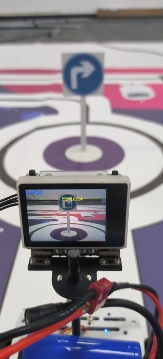
20

22

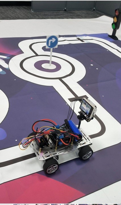
  1. The horn is recognized, because this car does not have a buzzer, so it is normal to patrol the line.
21

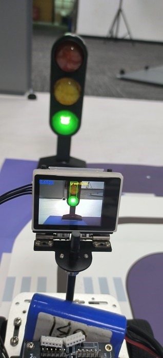
  1. Recognize traffic lights, red lights will stop, green lights will continue to move forward.
23

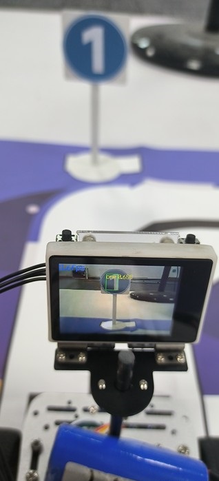
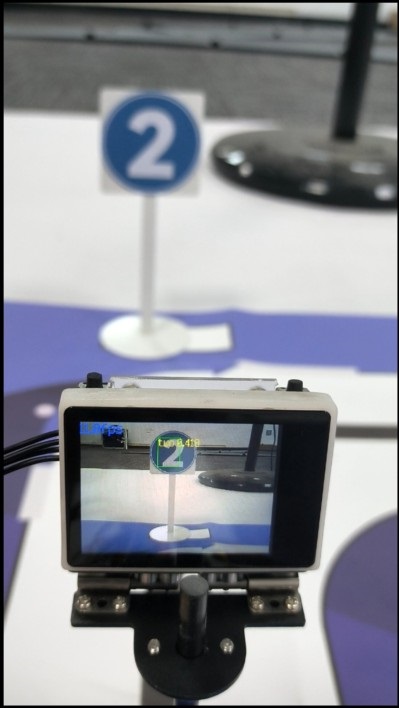
  1. Identify No. 1 and No. 2 garages, the car will enter No. 1 garage if it recognizes No. 1 garage; recognize No. 2 garage, and the car will reverse into No. 2 garage; 2 seconds after entering the garage, the car will come out and continue to patrol the line.
24

27

5.Notes about this routine

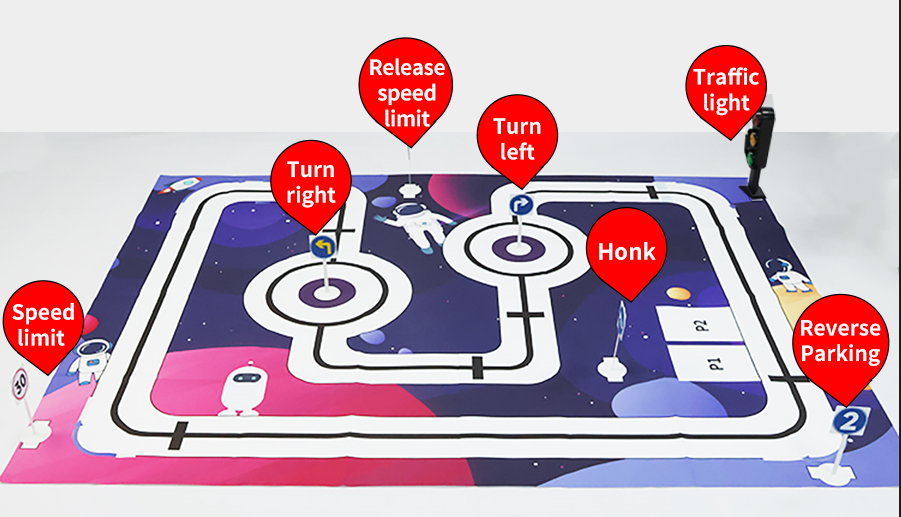
  1. The signposts placed on this tutorial map are shown in the figure below:
26

  1. The battery must be fully charged, otherwise it cannot work normally

  2. If the road signs cannot be recognized, you can adjust the bracket of the k210 or the distance of the road signs

  3. You must use the road sign model provided by us, refer to the pictures in the road sign folder, other road signs cannot be recognized

  4. Under normal circumstances, the motor is very smooth. If there is a motor jam or a large resistance, these conditions indicate that there is a problem with the motor.

    1. The patrol map must be kept clean without too many stains, otherwise it will affect the normal use
  5. When patrolling the line, the environment should not be too bright or too dark, normal lighting is fine

Identify parking spaces and park
MSPM0-Automatic Driving

COMPANY

  • About us
  • Team Style
  • Blog

LEARNING & EXPLORATION

  • Tutorials
  • Edge AI hardware
  • Educational robots
  • Embedded intelligent hardware

WHERE TO BUY

  • Yahboom Online Store
  • Amazon
  • Alibaba
  • AliExpress
  • Mercado

TECHNOLOGY SUPPORT

  • Email: support@yahboom.com

BE A DISTRIBUTOR

  • Email: sales@yahboom.com
QR Code

Copyright © 2017-2026 Yahboom. All Rights Reserved.

EN/中文