Welcome to K210 Module repository
4.Color reaction
4、Color reaction
4、Color reaction4.1 experiment description 4.2 experimental target4.3、experimental operation4.4 experimental results4.5 the experiments are summarized
4.1 experiment description
The present experiment was to belong to expand the class of experiments, the need to match other external devices to use, here to the car chassis and the ROS expansion Board is not part of K210 module kit contents, so the present experimental results are for reference only, if there is no corresponding device is not directly use the routine code.
ROS expansion Board needs advance programming firmware: ROS-CAR. hex
Due to the use of the motor voltage is 8. 4V, so the ROS expansion Board battery may not be inserted 12. 6V battery, you need to insert 8. 4V battery.
Trolley motor connected to the line as shown below:
Motor Motor 1 is connected to the Left Front wheel, the Motor Motor 2 is connected to the left rear wheel, motor Motor 3 is connected to the right front wheel, the Motor Motor 4 is connected to the right rear wheel.

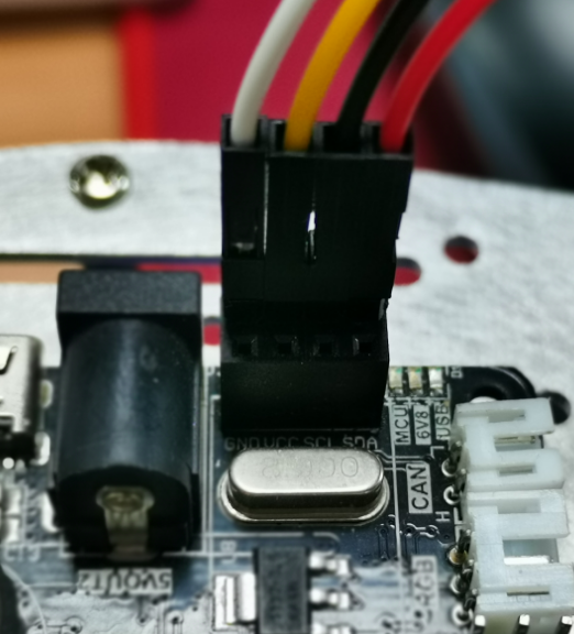
K210 module with the ROS expansion Board connected to the line sequence as shown below:
White(GND) connected to GND, yellow(5V) is connected to VCC, the black(RXD) connect the SCL, the red(TXD) connected to SDA.

Here you note that the illustration of the logo for the I2C line sequence identity, but K210 using serial communication, due to the burning of the ROS-CAR. the hex file has been put on this interface modification for the serial signal, so in fact the ROS expansion Board on the interface corresponding relationship is: the SCL is actually TX, SDA is actually RX.
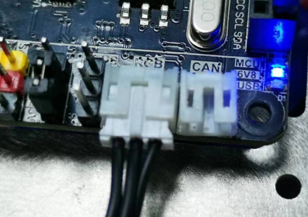
Insert the RGB light strip into the RGB light interface of the ROS expansion board.
4.2 experimental target
This lesson mainly learns the function of K210 module with car chassis to do visual inspection.
The reference code path for this experiment is :CanMV\06-export\color_rgb.py
4.3、experimental operation
ROS expansion Board to burn the firmware: ROS-CAR. hex
Insert the RGB light strip into the RGB light interface of the ROS expansion board.
Please CanMV\06-export\library directory under the trolley driver library and PID control Library in advance to download to the memory card root directory.
Open CanMV IDE and open the color_rgb.py code
The K210 module via the 4PIN cable is connected to the ROS expansion Board.
The trolley into the white background, breaking move K210 module bracket to a suitable angle, turn the car switch.
Please uncomment learning_color, then run the program again in CanMV IDE, and put the color to be recognized into the box for learning. After learning is completed, the serial terminal and display screen at the bottom of the IDE will display the recognized color value, and replace the recognized color value with the corresponding color value.
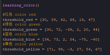
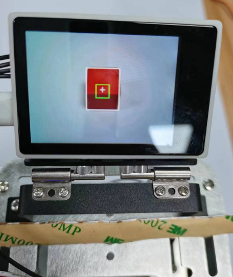
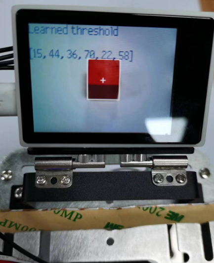
Run the program four times to update the values of threshold_red, threshold_green, threshold_blue, and threshold_yellow. When you're done, re-comment out the 'learning_color' function.
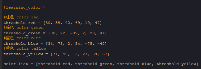
Finally, the program is downloaded into the K210 module to run.
4.4 experimental results
After the system is initialized, please put the red, green, blue or yellow color block in front of the camera view, and the car will automatically light the corresponding color according to the color of the current color block. If there are more than one color block, the car RGB light will show the running lantern effect.
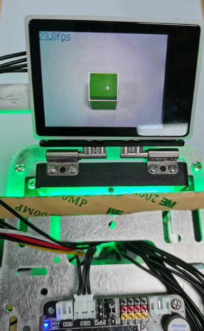
In order to display clearly, the light bar is placed on it. For practical application, please place the light bar according to the characteristics of the car.
4.5 the experiments are summarized
Due to the difference of light and product color in each place, the recognized color may not be recognized correctly. It is necessary to re-learn the color value according to its own color block to recognize it more accurately.