yahboom
HomeLearn
Solution
Blog
Online Store
About Us
EN/中文
K210 Module📖
0.Camera changes
  • Precautions for camera changes
1.K210-AI-Camera introduction
  • 1.K210 main chip introduction
  • 2.K210 visual recognition module introduction
  • 3.Module pin assignments
  • 4.MicroPython Introduction
  • 5. FAQ analysis
  • 6.Bracket installation
2.Development Environment Setup
  • 1.To install the serial port assistant
  • 2.Install CanMV IDE development software
  • 3.Flashcard factory firmware
  • 4.IDE import routine
  • 5.Call custom py library
  • 6.MicroPython API documentation
3.Basic experimental routines
  • 1.Lighting the RGB light experiment
  • 2.Key features of the experiment
  • 3.Timer experiment
  • 4.PWM breathing light experiment
  • 5.LCD display experiment
  • 6.The touchpad read the coordinates of the experiment
  • 7.The camera shows the experimental
  • 8.Memory card read and write files of the experiment
  • 9.External interface experimental
4.Graphical manipulation routines
  • 1.Draw graphics
  • 2.Button and the click event
  • 3.Slider
  • 4.Chart animation
  • 5.Multi-label layout
5.AI visual experiments routines
  • How to import the model file into memory cardnew
  • 1.Color recognition
  • 2.Barcode recognition
  • 3.QR code recognition
  • 4.Apriltags recognition
  • 5.Face detection
  • 6.Face feature detection
  • 7.Mask detection
  • 8.Face recognition
  • 9.Object detection
  • 10.Self-learning classification
  • 11.Handwritten digit recognition
  • 12. Multiple color recognition
  • 13. Human body detectionnew
  • 14. Yolo hand detectionnew
  • 15. License Plate Recognitionnew
  • 16. Autonomous training modelnew
6.Extended routines (sold separately)
6.1.For STM32 Car
  • 10. stm_ K210 Autonomous Learning Classification
  • 1.automatic driving
  • 2.color follow
  • 3.Handwriting digital operation
  • 4.Color reaction
  • 5.Road sign indicating the operation
  • 6.Following the apriltag
  • 7.QR code instruction
  • 8.PTZ tracking color
  • 9.PTZ tracking face
6.2.1 arduino_k210
  • 1.ard_k210-Color recognition
  • 2.ard_k210-Bar code identification
  • 3.ard_k210-QR code identification
  • 4.ard_ K210-mechanical code identification
  • 5.ard_ K210-Face Detection
  • 6. ard_ K210-facial feature detection
  • 7. ard_ K210-mask detection
  • 8. ard_ K210-facial recognition
  • 9. ard_ K210-object detection
  • 10. ard_ K210 Autonomous Learning Classification
  • 11. ard_ K210 Handwritten Digit Recognition
6.2 K210 as a coprocessor
  • ReadMe
6.2.2 stm32_k210
  • 1.stm_ K210 color recognition
  • 2. stm_ K210 barcode recognition
  • 3. stm_ K210 QR code recognition
  • 4. stm_ K210 mechanical code identification
  • 5. stm_ K210 Face Detection
  • 6.stm_ K210 facial feature detection
  • 7. stm_ K210 mask detection
  • 8. stm_ K210 facial recognition
  • 9. stm_ K210 object detection
  • 11. stm_ K210 Handwritten Digit Recognition
6.2.3 microbit_k210
  • 1.microbit_ K210 color recognition
  • 2.microbit_ K210 barcode recognition
  • 3.microbit_ K210 QR code recognition
  • 4.microbit_ K210 mechanical code identification
  • 5. microbit_ K210 Face Detection
  • 6. microbit_ K210 facial feature detection
  • 7. microbit_ K210 mask detection
  • 8. microbit_ K210 facial recognition
  • 9. microbit_ K210 object detection
  • 10. microbit_ K210 autonomous classification learning
  • 11. microbit_ K210 Handwritten Digit Recognition
6.2.4 pico_k210
  • 1. pico_ K210 color recognition
  • 2. Pico_ K210 barcode recognition
  • 3. Pico_ K210 QR code recognition
  • 4. pico_ K210 machine code recognition
  • 5. pico_ K210 Face Detection
  • 6. pico_ K210 facial feature detection
  • 7. pico_ K210 mask recognition
  • 8. pico_ K210 facial recognition
  • 9. pico_ K210 object detection
  • 10. pico_ K210 Autonomous Learning Classification
  • 11. pico_ K210 Handwritten Digit Recognition
6.2.5 MSPM0G3507_k210
  • 1.MSPM0_K210 color recognition
  • 2.MSPM0_K210 barcode recognition
  • 3.MSPM0_K210 QR code recognition
  • 4.MSPM0_K210 mechanical code recognition
  • 5.MSPM0_K210 face detection
  • 6.MSPM0_K210 facial feature detection
  • 7.MSPM0_K210 mask detection
  • 8.MSPM0_K210 face recognition
  • 9.MSPM0_K210 Object Detection
  • 10.MSPM0_K210 Self-study classification
  • 11.MSPM0_K210 handwritten digit recognition
6.2.6 MSPM0G3519_k210
  • 1. MSPM0_K210 Color Recognitionnew
  • 2. MSPM0_K210 Barcode Recognitionnew
  • 3. MSPM0_K210 QR Code Recognitionnew
  • 4. MSPM0_K210 Mechanical Code Recognitionnew
  • 5. MSPM0_K210 Face Detectionnew
  • 6. MSPM0_K210 Facial Feature Detectionnew
  • 7. MSPM0_K210 Mask Detectionnew
  • 8. MSPM0_K210 Face Recognitionnew
  • 9. MSPM0_K210 Object Detectionnew
  • 10. MSPM0_K210 Self-study Classificationnew
  • 11. MSPM0_K210 Handwritten Digit Recognitionnew
6.3 For 24 channel servo drive board
  • 1. 2DOF PTZ Color Tracking
  • 2. 2DOF Face Tracking
  • 3. 2DOF Fruit sorting
6.4 For autopilot map
  • 1.k210 model training
  • 2.Assembly and wiring of stm32 car
  • 3.Recognize left and right sign
  • 4.Identify and remove speed limit
  • 5.Identify parking spaces and park
  • 6.STM32 car autopilot
6.5.1 For MSPM0G3507_Wheeled Chassis Kit
  • 1.MSPM0-Automatic Driving
  • 2.MSPM0-Color follow
  • 3.MSPM0-Number recognition
  • 4.MSPM0-Color reaction
  • 5.MSPM0-Road signs
  • 6.MSPM0-Machine code following
  • 7.MSPM0-QR code recognition
6.5.2 For MSPM0G3519_Wheeled Chassis Kit
  • 1.MSPM0-Automatic Drivingnew
  • 2.MSPM0-Color follownew
  • 3.MSPM0-Number recognitionnew
  • 4.MSPM0-Color reactionnew
  • 5.MSPM0-Road signsnew
  • 6.MSPM0-Machine code followingnew
  • 7.MSPM0-QR code recognitionnew
6.5.3 For STM32_Wheeled Chassis Kit
  • 1.STM32-Automatic Driving
  • 2.STM32-Color follow
  • 3.STM32-Number recognition
  • 4.STM32-K210-Color Reaction
  • 5.STM32-Road signs
  • 6.STM32-Machine code following
  • 7.STM32-QR code recognition
Download
  • Driver development software
  • AI model
  • Source code
  • Instruction manual
  • Hardware_3DModelFile
  • K210_Chip_Data
Download ZIP

Welcome to K210 Module repository

9.External interface experimental

9 External interface experimental

9 External interface experimental9.1 the experimental goals 9.2 experimental procedure 9.3 experimental results 9.4 the experiments are summarized 9.5、Send and receive data using UART module

9.1 the experimental goals

This lesson mainly learns the function of microPython using external serial port communication.

The reference code path for this experiment is: CanMV\03-Hardware\serial.py

Since the current built-in ybserial module only supports sending data and does not support reading data, if you need the function of reading data, please refer to 9.5 to use the uart module to send and receive data.

9.2 experimental procedure

The factory firmware of the module has been integrated with the external serial port control module. If you have downloaded other firmware, please burn it back to the factory firmware before doing the experiment.

After using the matching wire connection, the corresponding color of the external pin is:
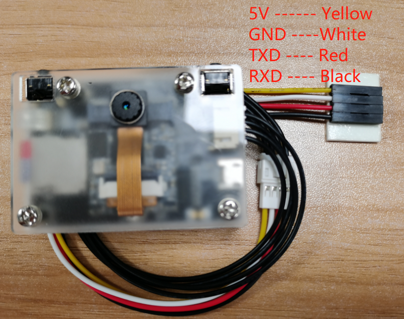
image-20230413105609919

The CH340 module needs to be used to connect the external interface of the module, and the pin connection is shown in the following figure.
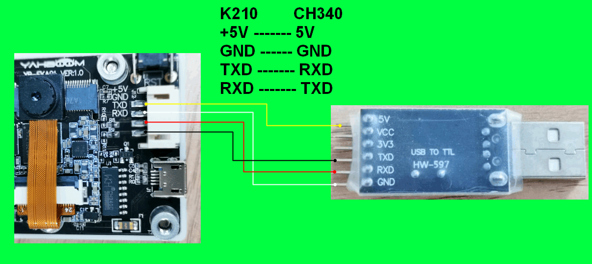
image-20230210160745161

  1. Import ybserial from modules.

from modules import ybserial 
import time 
  1. Create an object of ybserial and call it serial

xxxxxxxxxx
serial = ybserial() 
  1. Through the external serial port character 1 and newline character.

xxxxxxxxxx
serial.send_byte(0x31) 
serial.send_byte(0x0D) 
  
array = [0x30, 0x31, 0x32, 0x33, 0x0D] 
serial.send_bytearray(array) 

Wherein, serial.send_byte(data):Means to send one byte of data through the external serial port. The 'data' parameter ranges from 0-255.

serial.send_bytearray(array):Send a byte array through the external serial port. The argument 'array' is an array of bytes.

  1. Send the "Hello Yahboom" string through the external serial port.

xxxxxxxxxx
text = 'Hello Yahboom' 
num = serial.send(text) 
print("num:", num) 

Wherein, num = serial.send(string):Indicates sending a string through an external serial port, and the return value is the length of the string

  1. Create two command strings to send alternately, with count representing the number of times to send.

xxxxxxxxxx
num = 0 
count = 0 
CMD_1 = "$A#" 
CMD_2 = "$BB#" 
  1. Create a new while loop, the count is automatically added and the data is sent once every second. When the count is odd, the command CMD_1 is sent, and when the count is even, the command CMD_2 is sent.

xxxxxxxxxx
while True: 
    time.sleep_ms(1000) 
 count = count + 1 
 if count % 2 == 1: 
 num = serial. send(CMD_1) 
 else: 
 num = serial. send(CMD_2) 
 print("num:%d, count:%d" % (num, count)) 

9.3 experimental results

Connect the K210 module to the computer through the microUSB data cable, CanMV IDE click the connect button, after the connection is completed click the Run button to run the routine code. You can also download the code as main.py and run it in the K210 module.

Open the IDE at the bottom of the Serial TerminalThat you can see every second print data once.
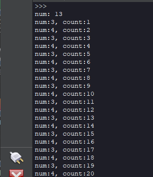
image-20230210171221867

Open the CH340 is connected to the serial port assistant, serial assistant configured as follows: baud rate 115000, no parity bit, 8 bits data, 1 bit stop, no flow control.
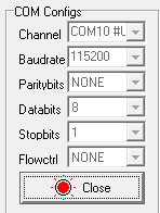
image-20230210171721614

You can see the serial port assistant every 1 second received sentence of command.
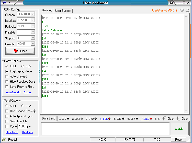
image-20230320203243371

9.4 the experiments are summarized

Use CanMV IDE, with the factory firmware write a good MicroPython syntax, the default already configured an external serial port, you'll need to initialize the serial port object can be used.

CH340 module needs to be manually connected to the line, insert the computer will produce another port, you need to and K210 port distinguish.

9.5、Send and receive data using UART module

The reference code path is: CanMV\03-Hardware\yb_uart.py

The ybserial module also calls the function of the UART module. To avoid conflicts, please do not use these two modules in the same program at the same time.

Code example:

from fpioa_manager import fm
from machine import UART
import time

# binding UART2 IO:6->RX, 8->TX
fm.register(6, fm.fpioa.UART2_RX)
fm.register(8, fm.fpioa.UART2_TX)

yb_uart = UART(UART.UART2, 115200, 8, 0, 0, timeout=1000, read_buf_len=4096)

write_bytes = b'$hello yahboom#\n'
last_time = time.ticks_ms()

try:
    while True:
        # send data per 500ms
        if time.ticks_ms() - last_time > 500:
            last_time = time.ticks_ms()
            yb_uart.write(write_bytes)
        # read and print data
        if yb_uart.any():
            read_data = yb_uart.read()
            if read_data:
                print("read_data = ", read_data)
except:
    pass

yb_uart.deinit()
del yb_uart

Among them, the external interface pins of the K210 module have been fixed as IO6 and IO8, IO6 corresponds to the receiving pin, and IO8 corresponds to the sending pin; the baud rate is set to 115200, and the serial port sends a string of $hello yahboom# characters every 500 milliseconds.
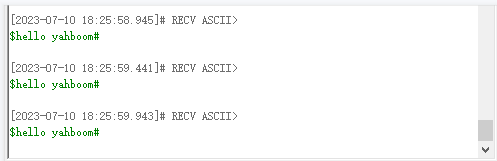
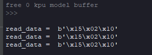
Monitor the incoming data from the serial port in real time, and print out the read data. If yb_uart.read() does not pass in parameters, it means to read all the buffered data of the serial port. If the parameter is 1, yb_uart.read(1) means to read a byte of data from the buffer area. If the parameter 2 is passed in, then Indicates reading two bytes of data from the buffer, and so on.
Memory card read and write files of the experiment
Draw graphics

COMPANY

  • About us
  • Team Style
  • Blog

LEARNING & EXPLORATION

  • Tutorials
  • Edge AI hardware
  • Educational robots
  • Embedded intelligent hardware

WHERE TO BUY

  • Yahboom Online Store
  • Amazon
  • Alibaba
  • AliExpress
  • Mercado

TECHNOLOGY SUPPORT

  • Email: support@yahboom.com

BE A DISTRIBUTOR

  • Email: sales@yahboom.com
QR Code
QR Code

Copyright © 2017-2026 Yahboom. All Rights Reserved.

EN/中文