yahboom
HomeLearn
Solution
Blog
Online Store
About Us
EN/中文
K210 Module📖
0.Camera changes
  • Precautions for camera changes
1.K210-AI-Camera introduction
  • 1.K210 main chip introduction
  • 2.K210 visual recognition module introduction
  • 3.Module pin assignments
  • 4.MicroPython Introduction
  • 5. FAQ analysis
  • 6.Bracket installation
2.Development Environment Setup
  • 1.To install the serial port assistant
  • 2.Install CanMV IDE development software
  • 3.Flashcard factory firmware
  • 4.IDE import routine
  • 5.Call custom py library
  • 6.MicroPython API documentation
3.Basic experimental routines
  • 1.Lighting the RGB light experiment
  • 2.Key features of the experiment
  • 3.Timer experiment
  • 4.PWM breathing light experiment
  • 5.LCD display experiment
  • 6.The touchpad read the coordinates of the experiment
  • 7.The camera shows the experimental
  • 8.Memory card read and write files of the experiment
  • 9.External interface experimental
4.Graphical manipulation routines
  • 1.Draw graphics
  • 2.Button and the click event
  • 3.Slider
  • 4.Chart animation
  • 5.Multi-label layout
5.AI visual experiments routines
  • How to import the model file into memory cardnew
  • 1.Color recognition
  • 2.Barcode recognition
  • 3.QR code recognition
  • 4.Apriltags recognition
  • 5.Face detection
  • 6.Face feature detection
  • 7.Mask detection
  • 8.Face recognition
  • 9.Object detection
  • 10.Self-learning classification
  • 11.Handwritten digit recognition
  • 12. Multiple color recognition
  • 13. Human body detectionnew
  • 14. Yolo hand detectionnew
  • 15. License Plate Recognitionnew
  • 16. Autonomous training modelnew
6.Extended routines (sold separately)
6.1.For STM32 Car
  • 10. stm_ K210 Autonomous Learning Classification
  • 1.automatic driving
  • 2.color follow
  • 3.Handwriting digital operation
  • 4.Color reaction
  • 5.Road sign indicating the operation
  • 6.Following the apriltag
  • 7.QR code instruction
  • 8.PTZ tracking color
  • 9.PTZ tracking face
6.2.1 arduino_k210
  • 1.ard_k210-Color recognition
  • 2.ard_k210-Bar code identification
  • 3.ard_k210-QR code identification
  • 4.ard_ K210-mechanical code identification
  • 5.ard_ K210-Face Detection
  • 6. ard_ K210-facial feature detection
  • 7. ard_ K210-mask detection
  • 8. ard_ K210-facial recognition
  • 9. ard_ K210-object detection
  • 10. ard_ K210 Autonomous Learning Classification
  • 11. ard_ K210 Handwritten Digit Recognition
6.2 K210 as a coprocessor
  • ReadMe
6.2.2 stm32_k210
  • 1.stm_ K210 color recognition
  • 2. stm_ K210 barcode recognition
  • 3. stm_ K210 QR code recognition
  • 4. stm_ K210 mechanical code identification
  • 5. stm_ K210 Face Detection
  • 6.stm_ K210 facial feature detection
  • 7. stm_ K210 mask detection
  • 8. stm_ K210 facial recognition
  • 9. stm_ K210 object detection
  • 11. stm_ K210 Handwritten Digit Recognition
6.2.3 microbit_k210
  • 1.microbit_ K210 color recognition
  • 2.microbit_ K210 barcode recognition
  • 3.microbit_ K210 QR code recognition
  • 4.microbit_ K210 mechanical code identification
  • 5. microbit_ K210 Face Detection
  • 6. microbit_ K210 facial feature detection
  • 7. microbit_ K210 mask detection
  • 8. microbit_ K210 facial recognition
  • 9. microbit_ K210 object detection
  • 10. microbit_ K210 autonomous classification learning
  • 11. microbit_ K210 Handwritten Digit Recognition
6.2.4 pico_k210
  • 1. pico_ K210 color recognition
  • 2. Pico_ K210 barcode recognition
  • 3. Pico_ K210 QR code recognition
  • 4. pico_ K210 machine code recognition
  • 5. pico_ K210 Face Detection
  • 6. pico_ K210 facial feature detection
  • 7. pico_ K210 mask recognition
  • 8. pico_ K210 facial recognition
  • 9. pico_ K210 object detection
  • 10. pico_ K210 Autonomous Learning Classification
  • 11. pico_ K210 Handwritten Digit Recognition
6.2.5 MSPM0G3507_k210
  • 1.MSPM0_K210 color recognition
  • 2.MSPM0_K210 barcode recognition
  • 3.MSPM0_K210 QR code recognition
  • 4.MSPM0_K210 mechanical code recognition
  • 5.MSPM0_K210 face detection
  • 6.MSPM0_K210 facial feature detection
  • 7.MSPM0_K210 mask detection
  • 8.MSPM0_K210 face recognition
  • 9.MSPM0_K210 Object Detection
  • 10.MSPM0_K210 Self-study classification
  • 11.MSPM0_K210 handwritten digit recognition
6.2.6 MSPM0G3519_k210
  • 1. MSPM0_K210 Color Recognitionnew
  • 2. MSPM0_K210 Barcode Recognitionnew
  • 3. MSPM0_K210 QR Code Recognitionnew
  • 4. MSPM0_K210 Mechanical Code Recognitionnew
  • 5. MSPM0_K210 Face Detectionnew
  • 6. MSPM0_K210 Facial Feature Detectionnew
  • 7. MSPM0_K210 Mask Detectionnew
  • 8. MSPM0_K210 Face Recognitionnew
  • 9. MSPM0_K210 Object Detectionnew
  • 10. MSPM0_K210 Self-study Classificationnew
  • 11. MSPM0_K210 Handwritten Digit Recognitionnew
6.3 For 24 channel servo drive board
  • 1. 2DOF PTZ Color Tracking
  • 2. 2DOF Face Tracking
  • 3. 2DOF Fruit sorting
6.4 For autopilot map
  • 1.k210 model training
  • 2.Assembly and wiring of stm32 car
  • 3.Recognize left and right sign
  • 4.Identify and remove speed limit
  • 5.Identify parking spaces and park
  • 6.STM32 car autopilot
6.5.1 For MSPM0G3507_Wheeled Chassis Kit
  • 1.MSPM0-Automatic Driving
  • 2.MSPM0-Color follow
  • 3.MSPM0-Number recognition
  • 4.MSPM0-Color reaction
  • 5.MSPM0-Road signs
  • 6.MSPM0-Machine code following
  • 7.MSPM0-QR code recognition
6.5.2 For MSPM0G3519_Wheeled Chassis Kit
  • 1.MSPM0-Automatic Drivingnew
  • 2.MSPM0-Color follownew
  • 3.MSPM0-Number recognitionnew
  • 4.MSPM0-Color reactionnew
  • 5.MSPM0-Road signsnew
  • 6.MSPM0-Machine code followingnew
  • 7.MSPM0-QR code recognitionnew
6.5.3 For STM32_Wheeled Chassis Kit
  • 1.STM32-Automatic Driving
  • 2.STM32-Color follow
  • 3.STM32-Number recognition
  • 4.STM32-K210-Color Reaction
  • 5.STM32-Road signs
  • 6.STM32-Machine code following
  • 7.STM32-QR code recognition
Download
  • Driver development software
  • AI model
  • Source code
  • Instruction manual
  • Hardware_3DModelFile
  • K210_Chip_Data
Download ZIP

Welcome to K210 Module repository

4.PWM breathing light experiment

4 PWM breathing light experiment

4 PWM breathing light experiment 4.1 experimental target 4.2 experimental procedure 4.3 experimental results 4.4 the experiments are summarized

4.1 experimental target

This lesson is mainly for learning microPython control PWM output function.

The present experiments the reference code path is: CanMV\03-Hardware\pwm.py

4.2 experimental procedure

Module factory firmware has been integrated PWM output module, if you download the other firmware, please burn back to the factory firmware and then perform the experiment.

  1. By machine import PWM and Timer.

from machine import Timer, PWM 
import time 
  1. Since the PWM signal needs to be the source of self-timer, so create a new timer object, Set the parameters for timer 0, channel 0, the PWM mode.

xxxxxxxxxx
tim = Timer(the Timer. TIMER0, Timer. CHANNEL0, mode=Timer. MODE_PWM) 
  1. By specifying the parameters of a new PWM object.

xxxxxxxxxx
pwm = the machine. PWM(tim, freq, duty, pin, enable=True) 
  • tim: Each PWM rely on a timer to generate a waveform, so there will need to pass a timer object the timer object must be initialized must be specified when the timer ID and channel number

  • freq: PWM waveform frequency

  • duty: PWM duty cycle, refers to the high level for the entire period the percentage of values: [0,100]

  • [pin]: PWM output pin. The actual physical pin of the IO number.

  • enable: Whether to immediately begin generating a waveform, the default bit True, And the object is generated immediately after the start at the specified pin to generate a PWM waveform

  1. Create a while loop, modify the duty cycle of the duty of values, so that the cycle changes from 0 to 100, from 100 down to 0, and then every time after the change of the duty of the output of the PWM duty cycle.

xxxxxxxxxx
duty=0
add = True
while True:
    if add:
        duty += 10
    else:
        duty -= 10
    if duty > 100:
        duty = 100
        add = False
    elif duty < 0:
        duty = 0
        add = True
    time.sleep(0.05)
    pwm.duty(duty)
  1. If you need to modify RGB lighting colors, please change the LED_PIN value, which corresponds to the color of the IO pins for the Red RED=27, Green GREEN=26, Blue BLUE=29 in.

xxxxxxxxxx
# RED=27, GREEN=26, BLUE=29 
LED_PIN = 26 

4.3 experimental results

Connect the K210 module to the computer through the microUSB data cable, CanMV IDE click the connect button, after the connection is completed click the Run button to run the routine code. You can also download the code as main.py and run it in the K210 module.

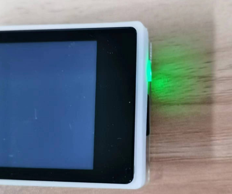
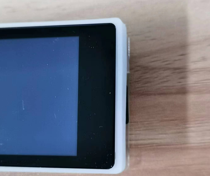
You can see the RGB lights green, and the last from the darkest to the brightest, and then from the brightest to the darkest regulation, rendering breathing light effect.
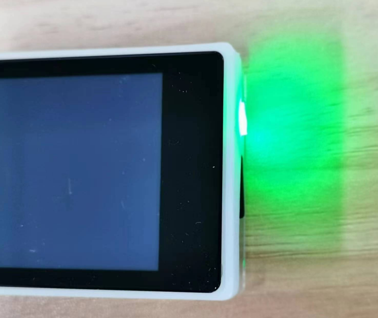
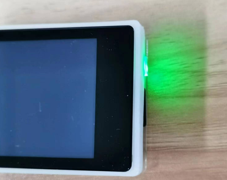
image-20230207164608556

image-20230207164626025

image-20230207164649667

image-20230207164707958

4.4 the experiments are summarized

Use CanMV IDE, with the factory firmware write a good MicroPython syntax, so that the control of the PWM outputs very easily, by a simple configuration of timer and PWM, and can show a breathing light effect. The PWM output is dependent on the timer, the current K210 a total of 3 timers, each timer has 4 channels, so up to 12 outputs a PWM signal. The PWM duty cycle for output high level with the cycle ratio.

Timer experiment
LCD display experiment

COMPANY

  • About us
  • Team Style
  • Blog

LEARNING & EXPLORATION

  • Tutorials
  • Edge AI hardware
  • Educational robots
  • Embedded intelligent hardware

WHERE TO BUY

  • Yahboom Online Store
  • Amazon
  • Alibaba
  • AliExpress
  • Mercado

TECHNOLOGY SUPPORT

  • Email: support@yahboom.com

BE A DISTRIBUTOR

  • Email: sales@yahboom.com
QR Code
QR Code

Copyright © 2017-2026 Yahboom. All Rights Reserved.

EN/中文