yahboom
HomeLearn
Solution
Blog
Online Store
About Us
EN/中文
K210 Module📖
0.Camera changes
  • Precautions for camera changes
1.K210-AI-Camera introduction
  • 1.K210 main chip introduction
  • 2.K210 visual recognition module introduction
  • 3.Module pin assignments
  • 4.MicroPython Introduction
  • 5. FAQ analysis
  • 6.Bracket installation
2.Development Environment Setup
  • 1.To install the serial port assistant
  • 2.Install CanMV IDE development software
  • 3.Flashcard factory firmware
  • 4.IDE import routine
  • 5.Call custom py library
  • 6.MicroPython API documentation
3.Basic experimental routines
  • 1.Lighting the RGB light experiment
  • 2.Key features of the experiment
  • 3.Timer experiment
  • 4.PWM breathing light experiment
  • 5.LCD display experiment
  • 6.The touchpad read the coordinates of the experiment
  • 7.The camera shows the experimental
  • 8.Memory card read and write files of the experiment
  • 9.External interface experimental
4.Graphical manipulation routines
  • 1.Draw graphics
  • 2.Button and the click event
  • 3.Slider
  • 4.Chart animation
  • 5.Multi-label layout
5.AI visual experiments routines
  • How to import the model file into memory cardnew
  • 1.Color recognition
  • 2.Barcode recognition
  • 3.QR code recognition
  • 4.Apriltags recognition
  • 5.Face detection
  • 6.Face feature detection
  • 7.Mask detection
  • 8.Face recognition
  • 9.Object detection
  • 10.Self-learning classification
  • 11.Handwritten digit recognition
  • 12. Multiple color recognition
  • 13. Human body detectionnew
  • 14. Yolo hand detectionnew
  • 15. License Plate Recognitionnew
  • 16. Autonomous training modelnew
6.Extended routines (sold separately)
6.1.For STM32 Car
  • 10. stm_ K210 Autonomous Learning Classification
  • 1.automatic driving
  • 2.color follow
  • 3.Handwriting digital operation
  • 4.Color reaction
  • 5.Road sign indicating the operation
  • 6.Following the apriltag
  • 7.QR code instruction
  • 8.PTZ tracking color
  • 9.PTZ tracking face
6.2.1 arduino_k210
  • 1.ard_k210-Color recognition
  • 2.ard_k210-Bar code identification
  • 3.ard_k210-QR code identification
  • 4.ard_ K210-mechanical code identification
  • 5.ard_ K210-Face Detection
  • 6. ard_ K210-facial feature detection
  • 7. ard_ K210-mask detection
  • 8. ard_ K210-facial recognition
  • 9. ard_ K210-object detection
  • 10. ard_ K210 Autonomous Learning Classification
  • 11. ard_ K210 Handwritten Digit Recognition
6.2 K210 as a coprocessor
  • ReadMe
6.2.2 stm32_k210
  • 1.stm_ K210 color recognition
  • 2. stm_ K210 barcode recognition
  • 3. stm_ K210 QR code recognition
  • 4. stm_ K210 mechanical code identification
  • 5. stm_ K210 Face Detection
  • 6.stm_ K210 facial feature detection
  • 7. stm_ K210 mask detection
  • 8. stm_ K210 facial recognition
  • 9. stm_ K210 object detection
  • 11. stm_ K210 Handwritten Digit Recognition
6.2.3 microbit_k210
  • 1.microbit_ K210 color recognition
  • 2.microbit_ K210 barcode recognition
  • 3.microbit_ K210 QR code recognition
  • 4.microbit_ K210 mechanical code identification
  • 5. microbit_ K210 Face Detection
  • 6. microbit_ K210 facial feature detection
  • 7. microbit_ K210 mask detection
  • 8. microbit_ K210 facial recognition
  • 9. microbit_ K210 object detection
  • 10. microbit_ K210 autonomous classification learning
  • 11. microbit_ K210 Handwritten Digit Recognition
6.2.4 pico_k210
  • 1. pico_ K210 color recognition
  • 2. Pico_ K210 barcode recognition
  • 3. Pico_ K210 QR code recognition
  • 4. pico_ K210 machine code recognition
  • 5. pico_ K210 Face Detection
  • 6. pico_ K210 facial feature detection
  • 7. pico_ K210 mask recognition
  • 8. pico_ K210 facial recognition
  • 9. pico_ K210 object detection
  • 10. pico_ K210 Autonomous Learning Classification
  • 11. pico_ K210 Handwritten Digit Recognition
6.2.5 MSPM0G3507_k210
  • 1.MSPM0_K210 color recognition
  • 2.MSPM0_K210 barcode recognition
  • 3.MSPM0_K210 QR code recognition
  • 4.MSPM0_K210 mechanical code recognition
  • 5.MSPM0_K210 face detection
  • 6.MSPM0_K210 facial feature detection
  • 7.MSPM0_K210 mask detection
  • 8.MSPM0_K210 face recognition
  • 9.MSPM0_K210 Object Detection
  • 10.MSPM0_K210 Self-study classification
  • 11.MSPM0_K210 handwritten digit recognition
6.2.6 MSPM0G3519_k210
  • 1. MSPM0_K210 Color Recognitionnew
  • 2. MSPM0_K210 Barcode Recognitionnew
  • 3. MSPM0_K210 QR Code Recognitionnew
  • 4. MSPM0_K210 Mechanical Code Recognitionnew
  • 5. MSPM0_K210 Face Detectionnew
  • 6. MSPM0_K210 Facial Feature Detectionnew
  • 7. MSPM0_K210 Mask Detectionnew
  • 8. MSPM0_K210 Face Recognitionnew
  • 9. MSPM0_K210 Object Detectionnew
  • 10. MSPM0_K210 Self-study Classificationnew
  • 11. MSPM0_K210 Handwritten Digit Recognitionnew
6.3 For 24 channel servo drive board
  • 1. 2DOF PTZ Color Tracking
  • 2. 2DOF Face Tracking
  • 3. 2DOF Fruit sorting
6.4 For autopilot map
  • 1.k210 model training
  • 2.Assembly and wiring of stm32 car
  • 3.Recognize left and right sign
  • 4.Identify and remove speed limit
  • 5.Identify parking spaces and park
  • 6.STM32 car autopilot
6.5.1 For MSPM0G3507_Wheeled Chassis Kit
  • 1.MSPM0-Automatic Driving
  • 2.MSPM0-Color follow
  • 3.MSPM0-Number recognition
  • 4.MSPM0-Color reaction
  • 5.MSPM0-Road signs
  • 6.MSPM0-Machine code following
  • 7.MSPM0-QR code recognition
6.5.2 For MSPM0G3519_Wheeled Chassis Kit
  • 1.MSPM0-Automatic Drivingnew
  • 2.MSPM0-Color follownew
  • 3.MSPM0-Number recognitionnew
  • 4.MSPM0-Color reactionnew
  • 5.MSPM0-Road signsnew
  • 6.MSPM0-Machine code followingnew
  • 7.MSPM0-QR code recognitionnew
6.5.3 For STM32_Wheeled Chassis Kit
  • 1.STM32-Automatic Driving
  • 2.STM32-Color follow
  • 3.STM32-Number recognition
  • 4.STM32-K210-Color Reaction
  • 5.STM32-Road signs
  • 6.STM32-Machine code following
  • 7.STM32-QR code recognition
Download
  • Driver development software
  • AI model
  • Source code
  • Instruction manual
  • Hardware_3DModelFile
  • K210_Chip_Data
Download ZIP

Welcome to K210 Module repository

3.Timer experiment

3 Timer experiment

3 Timer experiment 3.1 the experimental goals 3.2 experimental procedure 3.3 experimental results 3.4 the experiments are summarized

3.1 the experimental goals

This lesson is mainly learning K210 timer function.

The present experiments the reference code path is: CanMV\03-Hardware\timer.py

3.2 experimental procedure

Module factory firmware has been integrated Timer Timer module, if you download the other firmware, please burn back to the factory firmware and then perform the experiment.

  1. By machine import Timer.

from machine import Timer 
import time 
  1. Create a Timer object, and the name of the timer.

xxxxxxxxxx
timer = the machine. Timer(id, channel, mode=Timer. MODE_ONE_SHOT, period=1000, unit=Timer. UNIT_MS, callback=None, arg=None, start=True, priority=1, div=0) 

Parameters of content:

  • id: Timer ID, [0~2] (the Timer. TIMER0~TIMER2)

  • channel: Timer, channel [Timer. CHANNEL0~Timer. CHANNEL3]

  • mode: Timer mode, MODE_ONE_SHOT Or MODE_PERIODIC Or MODE_PWM

  • period: Timer cycle, after starting the timer period Time, the callback function will be called, (0,~)

  • unit: Sets the cycle of the unit, the default bit milliseconds ms, and Timer.UNIT_S Or Timer.UNIT_MS Or Timer.UNIT_US Or Timer.UNIT_NS

  • callback: Timer callback function, defined by two parameters, one is the timer object Timer And the second is in the definition of the object is the desired parameters to pass argMore please argParameter explanation

Note: the callback function is the interrupt is called, so in the callback function, please do not take too long time and do dynamic allocation of Switch interrupt operation

  • arg: Hope passed to the callback function parameter as a callback function as the second parameter

  • start: Whether the object was successfully constructed immediately after the start of the timer, True: Immediate start; False:Do not immediately turn on, you need to call start()Function to start the timer

  • priority: Hardware timer interrupt priority levels, with a particular CPU related, in the K210, take values in the range[1,7], the smaller the value the higher the priority

  • div: Hardware timer frequency divider, the value range is[0,255], the default is 0, clk_timer(timer clock frequency = clk_pll0(Phase-Locked Loop 0 frequency/2^(div+1)

  1. The new timer callback function on_timer, inside print debugging information. And set the timer every 100 milliseconds called once on_timer。

Note: the callback function is the interrupt is called, print debug information will take longer CPU time, here just as in the demo, the actual development process do not interrupt the printing of debugging information.

xxxxxxxxxx
def on_timer(timer): 
    print("This is on_timer callback") 
  
timer = Timer(the Timer. TIMER0, Timer. CHANNEL0, 
    mode=Timer. MODE_PERIODIC, period=100, 
    unit=the Timer. UNIT_MS, callback=on_timer, arg=None) 
  1. Create a new last_time variable for storing the current system time stamp, the units are milliseconds.

xxxxxxxxxx
last_time = time. ticks_ms() 
  1. Create a while loop that lets the system every 200 milliseconds, print a debug message. And at the end of the program or exit the timer is shut off.

xxxxxxxxxx
try: 
     while True: 
         if time. ticks_ms() - last_time >= 200: 
         last_time = time. ticks_ms() 
         print("This is main loop") 
except: 
     timer. deinit() 
     del timer 

3.3 experimental results

Connect the K210 module to the computer through the microUSB data cable, CanMV IDE click the connect button, after the connection is completed click the Run button to run the routine code. You can also download the code as main.py and run it in the K210 module.

Point the opening at the bottom of the Serial Terminal,You can see the print out debugging information. Since the timer is every 100 milliseconds of the print data once, whereas a while loop is for every 200 seconds printed data once, so the final look of the effect of each print once the loop information, it will print two times the timer information.
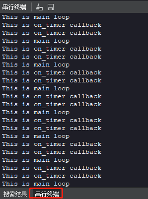
image-20230207142729637

3.4 the experiments are summarized

Use CanMV IDE, with the factory firmware write a good MicroPython syntax, so that the control K210 timer very easy, just by the simple configuration of the timers, set the timer for the channel, period and the callback function, etc., you can call the normal timer, to avoid the timer callback function in the processing takes too long things should be as simple and fast process to finish things, and finally at the end of the program when you need to call the deinit function allows the timer to restore the default, otherwise the timer callback function does not stop automatically.

Key features of the experiment
PWM breathing light experiment

COMPANY

  • About us
  • Team Style
  • Blog

LEARNING & EXPLORATION

  • Tutorials
  • Edge AI hardware
  • Educational robots
  • Embedded intelligent hardware

WHERE TO BUY

  • Yahboom Online Store
  • Amazon
  • Alibaba
  • AliExpress
  • Mercado

TECHNOLOGY SUPPORT

  • Email: support@yahboom.com

BE A DISTRIBUTOR

  • Email: sales@yahboom.com
QR Code

Copyright © 2017-2026 Yahboom. All Rights Reserved.

EN/中文