Welcome to 310 Motor repository
3.1 Control motor
12. Control the forward and reverse rotation of the motor
12. Control the forward and reverse rotation of the motor 12.1. Experimental purpose 12.2. Configuration pin information 12.3. Analysis of the experimental flow chart 12.4. core code explanation 12.5. hardware connection 12.6. Experimental effect
12.1. Experimental purpose
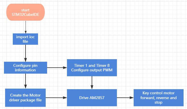
Using the timer function of STM32, the motor driver chip AM2857 is driven to control the forward rotation, reverse rotation and stop of the motor.
12.2. Configuration pin information
- Import the ioc file from the Beep project and name it Motor.
According to the schematic diagram, there are a total of four AM2857 motor driver modules, one motor driver module controls one motor, and the pin configuration is shown in the figure below.
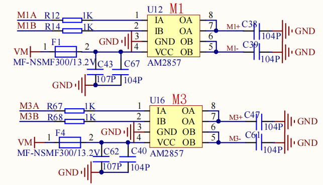
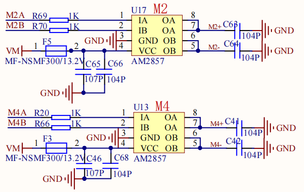
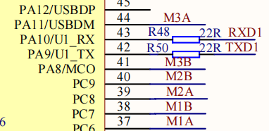

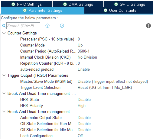
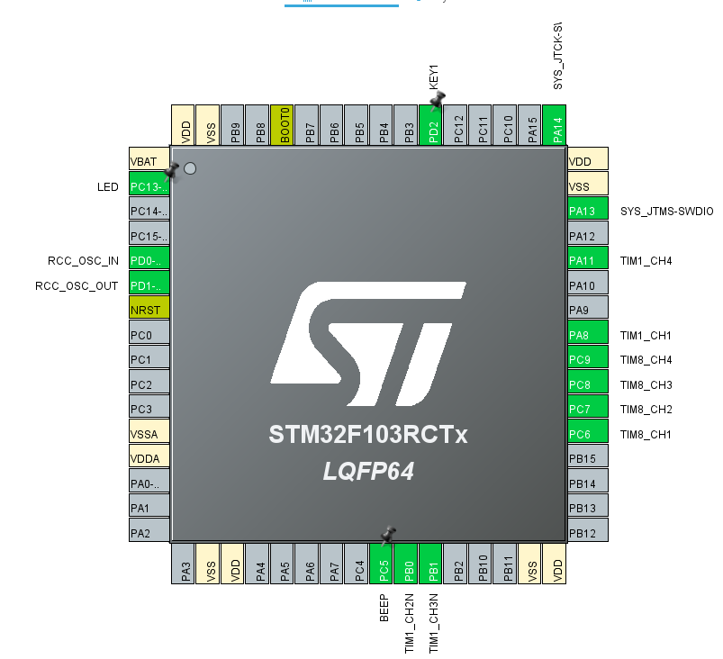
- First set timer 1, select the internal clock as the clock source, and set the corresponding pins of the four channels to output PWM signals CH1 CH2N CH3N CH4 PA8 PB0 PB1 PA11.
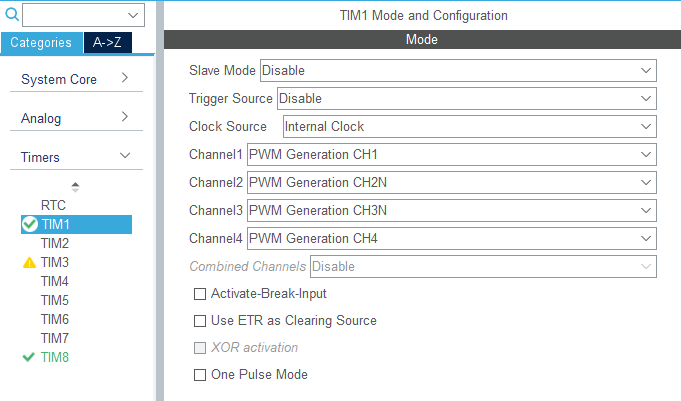
Other parameters are shown in the figure below:
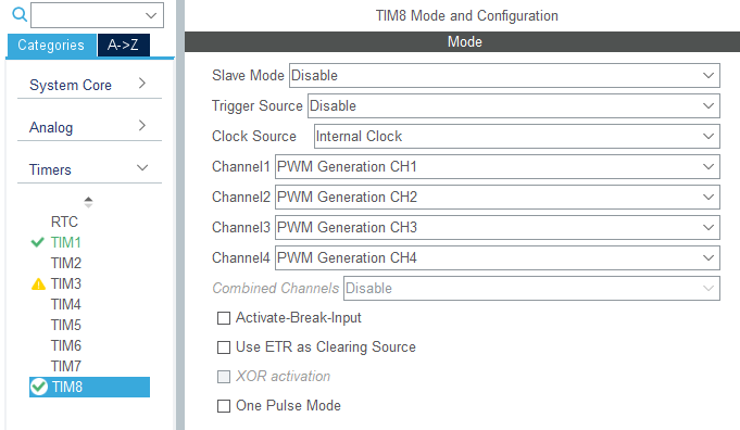
- Next, set timer 8, select the internal clock as the clock source, and set the corresponding pins of the four channels to output PWM signals CH1 CH2 CH3 CH4 PC6 PC7 PC8 PC9.
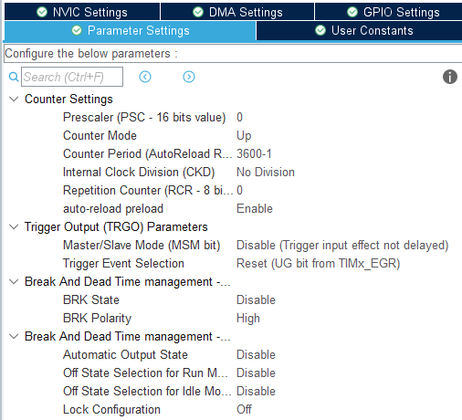
Other parameters are the same as timer 1.
The final chip configuration pins are shown in the figure below:
12.3. Analysis of the experimental flow chart
12.4. core code explanation
- Create new bsp_motor.h and bsp_motor.c, and add the following content to bsp_motor.h:
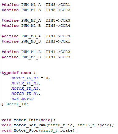
Among them, M1 corresponds to the motor in the upper left corner of the body, M2 corresponds to the motor in the lower left corner, M3 corresponds to the motor in the upper right corner, and M4 corresponds to the motor in the lower right corner.
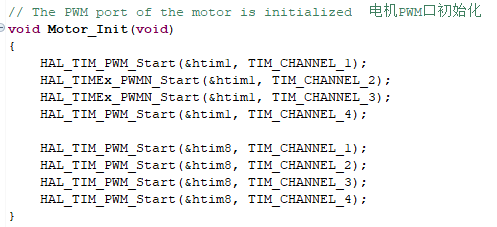
- Create the following content in the bsp_motor.c file:
The motor timer PWM output starts initialization.
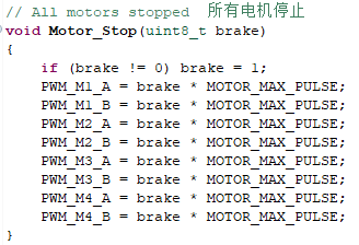
- Motor stop function, parameter brake=1 means brake stop, brake=0 means free stop.
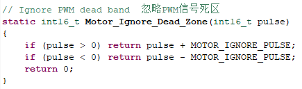
- Since the motor has a certain control dead zone, the dead zone can be filtered. If you choose not to filter, please define the MOTOR_IGNORE_PULSE parameter to 0.
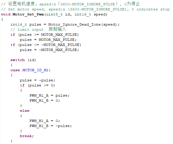
- The next step is to set the motor speed, where id is the motor ID, speed speed value range: ±(3600-MOTOR_IGNORE_PULSE), 0 is stop.
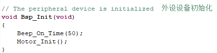
- Add the content of motor initialization in the Bsp_Init() function.
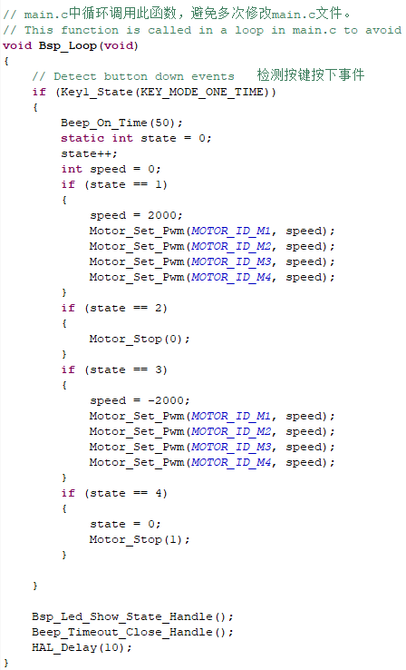
- Add the function of button to control the motor in the Bsp_Loop() function, press the first time to go forward, the second time to free stop, the third time to retreat, and the fourth time to brake to stop.
12.5. hardware connection
The motor connecting line needs to be connected to the corresponding motor as shown in the figure below, otherwise it may cause the problem that the program does not match the phenomenon. Motor 1 corresponds to the motor in the upper left corner of the body, Motor 2 corresponds to the motor in the lower left corner, Motor 3 corresponds to the motor in the upper right corner, and Motor 4 corresponds to the motor in the lower right corner.
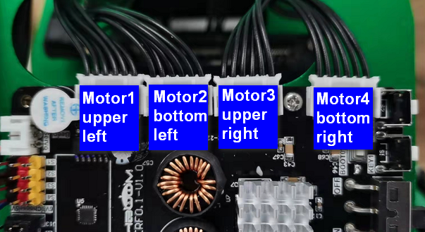
Since the power of the motor is relatively large, the expansion board should not be powered by USB 5V directly, but must be powered by DC 12V.
12.6. Experimental effect
Since the motor will turn when started, please stand up the trolley before the experiment, and the motor wheels are suspended in the air to avoid rampage.
After the program is programmed, the LED light flashes every 200 milliseconds. Press the first forward, the second free stop, the third backward, and the fourth brake to stop.