yahboom
HomeLearn
Solution
Blog
Online Store
About Us
EN/中文
310 Motor📖
1.Hardware parameter
  • Hardware parameter
2.ROS robot control board tutorials
  • 3.0 ReadMe
  • 3.1 Control motor
  • 3.2 Timer got encoder data
  • 3.3 PID control robot movement
  • 3.4 4WD Robot kinematics analysis
  • 3.5 Ackerman Robot kinematics analysis
  • 3.6 Mecanum wheel kinematics analysis
3.STM32 smart car tutorials
0. Get started quickly
  • 14.Infrared sensor obstacle avoidance
  • 0. Installation Instructions
  • 1. Version configuration
  • 2. Smart car installation video
  • 3. Precautions for use
1. Introduction to STM32 board
  • 1. Learn about STM32
  • 2. Introduction to STM32 development board
  • 3. Development board pin assignment
  • 4. Introduction to HAL library and LL library
2. Development environment
  • 1. Common development tools
  • 2. STM32CubeMX Install - Use
  • 3. STM32CubeIDE Install - Use
  • 4. Common Driver Installation
  • 5. Program download and simulation
  • 6. Engineering experience and migration
3. Car expansion tutorial
  • 1.Servo control
  • 2.Basic use ultrasonic servo PTZ
  • 3.Motor control
  • 4.OLED display light sensitivity value
  • 5.Infrared sensor
  • 6.Four-way tracking module
  • 7.Infrared remote control
  • 8.Ultrasonic ranging
  • 9.PS2 controller test
  • 10.Car line patrol
  • 11.Ultrasonic follow
  • 12.Ultrasonic obstacle avoidance
  • 13.Ultrasonic obstacle avoidance (servo PTZ version)
  • 15.Infrared remote control
  • 16.PS2 handle remote control
4.2-channel motor drive module tutorial
  • 2.1 Introduction of Module
  • 2.2 For STM32
  • 2.3 For Arduino
  • 2.4 For RaspberryPi
  • 2.5 For RaspberryPi Pico
  • 2.6 For jetson nano
  • 2.7 For MSPM0G3507
  • 2.8 For MSPM0G3519new
5.4-channel motor drive tutorials
Introduction and debugging
  • 0.Motor introduction and usage
  • 1.Introduction to 4-channel motor drive board
  • 2.Control command
  • 3.PC host
USART communication
  • For Arduino
  • For Jetson NANO
  • For MSPM0G3507
  • For MSPM0G3519new
  • For PICO2
  • For RDK X5
  • For RPi5
  • For STM32
IIC communication
  • For Arduino
  • For ESP32
  • For ESP32
  • For Jetson NANO
  • For MSPM0G3507
  • For MSPM0G3519new
  • For PICO2
  • For RDK X5
  • For RPi5
  • For STM32
Download
  • Motor_3D_Model_File
  • Annex_ROSRobotControlBoard
  • Annex_STM3RobotCar
  • Annex_2-channelMotorDriveModule
  • Annex_4-channelMotorDriveModule
Download ZIP

Welcome to 310 Motor repository

3.5 Ackerman Robot kinematics analysis

14.2 Kinematics Analysis of Ackermann Car

14.2.1、Ackerman car model introduction

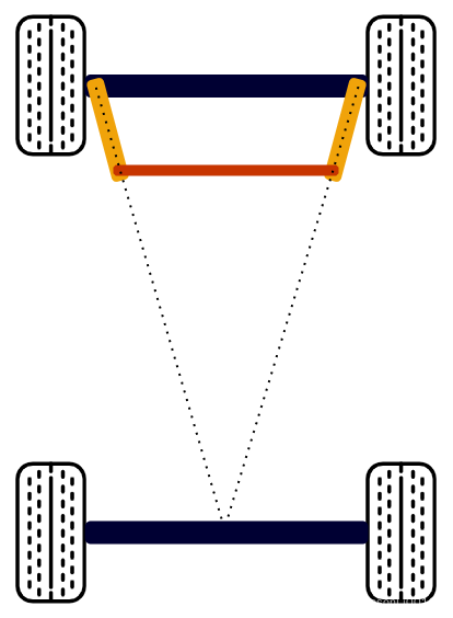
The whole vehicle has a total of 4 wheels, the front 2 wheels are steering gear steering wheels, and the rear 2 wheels are driving wheels, which are mainly responsible for the overall movement. The difference from other types of cars is that it has its own unique steering gear, while other types of cars adjust the turning through the differential speed of the left and right wheels. The main parameters of Ackerman models include left and right wheelbase, front and rear wheel spacing and turning radius.

 

14.2.2、Ackerman structural dynamics model

Ackermann Model Steering Features:

  • When driving before, the axes of the 4 wheels are parallel to each other and perpendicular to the longitudinal center plane of the vehicle body;
  • During the turning process, all 4 wheels must make a circular motion around an instantaneous center point.

When the Ackerman model is turning, the angles of the inner and outer wheels are different, and the turning radius of the inner tire is smaller than that of the outer tire, as shown in the figure below.
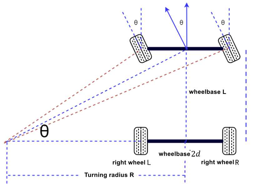
Among them, β is the turning angle of the front outer wheel of the car, α is the turning angle of the front inner wheel of the car, K is the wheelbase, L is the wheelbase, and R is the minimum turning radius. The minimum turning radius is a very important parameter in the Ackerman motion model. From this, the Ackerman core formula can be derived:

cotβ−cotα=K/L

Minimum turning radius R:

In low-speed environments,

The turning radius of the vehicle's travel path changes slowly, and at this time we can assume that the rate of change of direction of the vehicle is equal to the angular velocity of the vehicle. Then the angular velocity of the vehicle is following.

()ω=V/R(1.1)

Using the relationship between the wheelbase L and the front wheel angle θ can be obtained,

()1/R=θ/L(1.2)

When the slip angle (the angle formed between the direction of travel of the car and the direction of the rim) is small and the slip angle of the rear wheel is 0, combining 1.1 and 1.2 can be obtained,

ω/V≈1/R=θ/L

The steering radius of the inner and outer tires is different.

()β=L/(R+K/2)
()α=L/(R−K/2)

Then it can be obtained that the front wheel rotation angle θ is

()θ=(β+α)/2≈L/R

The minimum turning radius R is

R=L/θ

The position of the vehicle is predicted from the minimum turning radius:

Assuming that in the vehicle coordinate system, the vehicle speed is v, the distance moved in t time is v*t, and the direct turning radius is R, it can be calculated that the angle the vehicle has turned is σ,

σ=v∗t/R

Combined with the turning radius R calculated above, it can be obtained

σ=v∗t/θ/L

Then in the vehicle coordinate system, the vehicle position coordinates after time t are updated as

x(t+1)=R∗(1−cos(σ))
y(t+1)=R∗sin(σ)


4WD Robot kinematics analysis
Mecanum wheel kinematics analysis

COMPANY

  • About us
  • Team Style
  • Blog

LEARNING & EXPLORATION

  • Tutorials
  • Edge AI hardware
  • Educational robots
  • Embedded intelligent hardware

WHERE TO BUY

  • Yahboom Online Store
  • Amazon
  • Alibaba
  • AliExpress
  • Mercado

TECHNOLOGY SUPPORT

  • Email: support@yahboom.com

BE A DISTRIBUTOR

  • Email: sales@yahboom.com
QR Code
QR Code

Copyright © 2017-2026 Yahboom. All Rights Reserved.

EN/中文