yahboom
HomeLearn
Solution
Blog
Online Store
About Us
EN/中文
310 Motor📖
1.Hardware parameter
  • Hardware parameter
2.ROS robot control board tutorials
  • 3.0 ReadMe
  • 3.1 Control motor
  • 3.2 Timer got encoder data
  • 3.3 PID control robot movement
  • 3.4 4WD Robot kinematics analysis
  • 3.5 Ackerman Robot kinematics analysis
  • 3.6 Mecanum wheel kinematics analysis
3.STM32 smart car tutorials
0. Get started quickly
  • 14.Infrared sensor obstacle avoidance
  • 0. Installation Instructions
  • 1. Version configuration
  • 2. Smart car installation video
  • 3. Precautions for use
1. Introduction to STM32 board
  • 1. Learn about STM32
  • 2. Introduction to STM32 development board
  • 3. Development board pin assignment
  • 4. Introduction to HAL library and LL library
2. Development environment
  • 1. Common development tools
  • 2. STM32CubeMX Install - Use
  • 3. STM32CubeIDE Install - Use
  • 4. Common Driver Installation
  • 5. Program download and simulation
  • 6. Engineering experience and migration
3. Car expansion tutorial
  • 1.Servo control
  • 2.Basic use ultrasonic servo PTZ
  • 3.Motor control
  • 4.OLED display light sensitivity value
  • 5.Infrared sensor
  • 6.Four-way tracking module
  • 7.Infrared remote control
  • 8.Ultrasonic ranging
  • 9.PS2 controller test
  • 10.Car line patrol
  • 11.Ultrasonic follow
  • 12.Ultrasonic obstacle avoidance
  • 13.Ultrasonic obstacle avoidance (servo PTZ version)
  • 15.Infrared remote control
  • 16.PS2 handle remote control
4.2-channel motor drive module tutorial
  • 2.1 Introduction of Module
  • 2.2 For STM32
  • 2.3 For Arduino
  • 2.4 For RaspberryPi
  • 2.5 For RaspberryPi Pico
  • 2.6 For jetson nano
  • 2.7 For MSPM0G3507
  • 2.8 For MSPM0G3519new
5.4-channel motor drive tutorials
Introduction and debugging
  • 0.Motor introduction and usage
  • 1.Introduction to 4-channel motor drive board
  • 2.Control command
  • 3.PC host
USART communication
  • For Arduino
  • For Jetson NANO
  • For MSPM0G3507
  • For MSPM0G3519new
  • For PICO2
  • For RDK X5
  • For RPi5
  • For STM32
IIC communication
  • For Arduino
  • For ESP32
  • For ESP32
  • For Jetson NANO
  • For MSPM0G3507
  • For MSPM0G3519new
  • For PICO2
  • For RDK X5
  • For RPi5
  • For STM32
Download
  • Motor_3D_Model_File
  • Annex_ROSRobotControlBoard
  • Annex_STM3RobotCar
  • Annex_2-channelMotorDriveModule
  • Annex_4-channelMotorDriveModule
Download ZIP

Welcome to 310 Motor repository

3.3 PID control robot movement

15. PID control robot movement

15. PID control robot movement 15.1. Experimental purpose 15.2. configuration pin information 15.3. Analysis of the experimental flow chart 15.4. core code explanation 15.5. hardware connection 15.6. Experimental effect

15.1. Experimental purpose

Control the movement of the robot, and control the running speed of the robot through the PID algorithm.

Since different models require different drive codes, here we only take the Mecanum wheel trolley as an example.

15.2. configuration pin information

  1. Import the ioc file from the Encoder project and name it Car_Motion.

No additional content is required, and the final chip configuration pins are shown in the following figure:
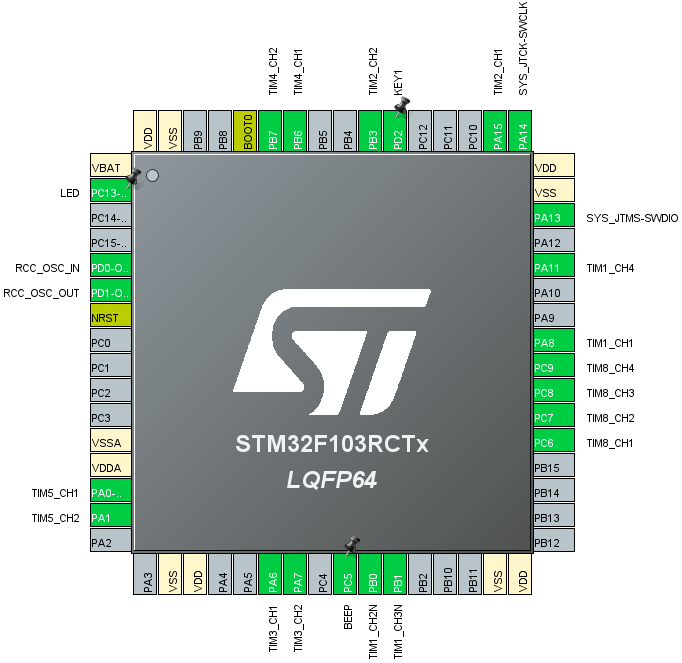
image-20220311171929134

15.3. Analysis of the experimental flow chart
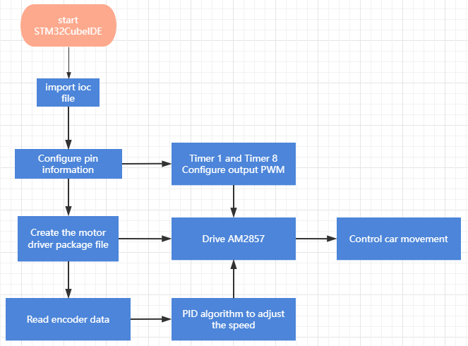
image-20220519113617358

15.4. core code explanation

  1. Create new bsp_pid.h and bsp_pid.c, and add the following content to bsp_pid.h:
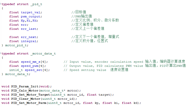
image-20220311182153477

  1. Create the following content in the bsp_pid.c file:

Initialize PID parameters:
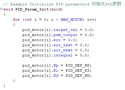
image-20220311182232217

  1. Calculation formula of incremental PID.
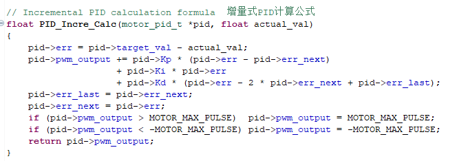
image-20220311182312127

  1. Set the target value.

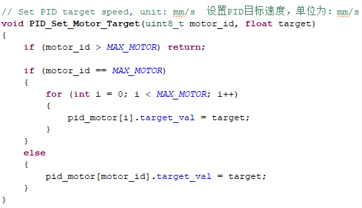
image-20220311182400564

  1. Calculate the PWM output value through PID calculation.

image-20220311182458461

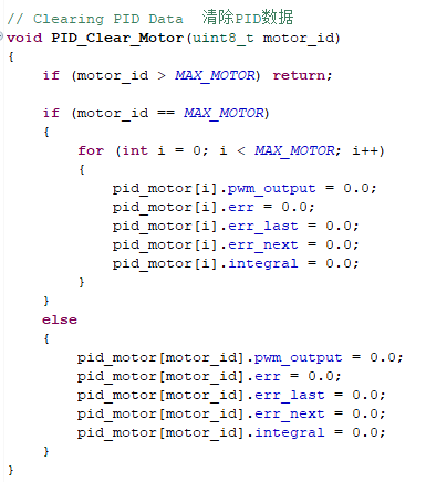
  1. Clear the PID parameter data.

image-20220311182542931

  1. Create new bsp_motion.h and bsp_motion.c files.
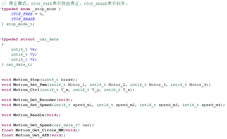
image-20220311183152424

  1. Get and calculate the speed of the trolley from the encoder.
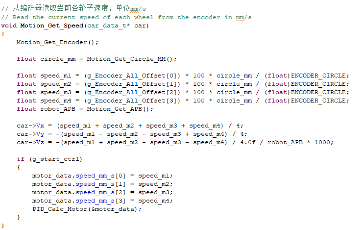
image-20220325115058394

  1. Re-update the PWM data of the motor according to the speed value, so as to achieve the effect of speed regulation.
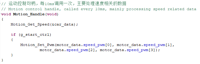
image-20220325115219282

15.5. hardware connection

The motor connecting line needs to be connected to the corresponding motor as shown in the figure below, otherwise it may cause the problem that the program does not match the phenomenon. Motor 1 corresponds to the motor in the upper left corner of the body, Motor 2 corresponds to the motor in the lower left corner, Motor 3 corresponds to the motor in the upper right corner, and Motor 4 corresponds to the motor in the lower right corner.
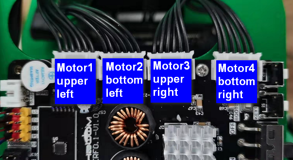
image-20220311143208773

Since the power of the motor is relatively large, the expansion board should not be powered by USB 5V directly, but must be powered by DC 12V.

15.6. Experimental effect

Since the motor will turn when started, please stand up the trolley before the experiment, and the motor wheels are suspended in the air to avoid rampage.

After the program is programmed, the LED light flashes every 200 milliseconds. Press the button KEY1 once, the car moves forward, and press the KEY1 button again to stop the car.

Timer got encoder data
4WD Robot kinematics analysis

COMPANY

  • About us
  • Team Style
  • Blog

LEARNING & EXPLORATION

  • Tutorials
  • Edge AI hardware
  • Educational robots
  • Embedded intelligent hardware

WHERE TO BUY

  • Yahboom Online Store
  • Amazon
  • Alibaba
  • AliExpress
  • Mercado

TECHNOLOGY SUPPORT

  • Email: support@yahboom.com

BE A DISTRIBUTOR

  • Email: sales@yahboom.com
QR Code
QR Code

Copyright © 2017-2026 Yahboom. All Rights Reserved.

EN/中文