yahboom
HomeLearn
Solution
Blog
Online Store
About Us
EN/中文
MicroROS Robot📖
01. Introduction
  • 0.Unpacking and reviewing video
  • 1. ReadMe - learning route
  • 2. Introduction to lidar
  • 3. Introduction to microROS control board
  • 4. FAQ
  • 5. About charging
02. Assembly course
  • Assembly steps
03. Preparation
  • First Trial
  • 1. Write firmware
  • 2. How to install and use VM
  • 3. microROS control board configuration
  • 4. Connect to microROS agent
04. VM Remote control course
  • 1. VM keyboard remote control
  • 2. VM handle remote control
05.ROS-WiFi module configuration
  • 0. Serial port configuration WiFi instructions
  • 1.Module usage in car(ReadMe)
  • 2.Connection module proxy
  • 3.Camera picture correction(ReadMe)
  • 4.Calibrate servo PTZ(ReadMe)
06.ROS+OpenCV course
  • 1.OpenCV Getting started
  • 2.Geometric transformation
  • 3.Image processing and drawing text line segments
  • 4.Image beautification
07.Mediapipe course
  • 1. Hand detection
  • 2. Posture detection
  • 3. Overall inspection
  • 4. Face detection
  • 5. Face recognition
  • 6. Facial effects
  • 7. 3D object recognition
  • 8. Brush
  • 9. Finger control
  • 10. Gesture recognition
08. Robot basic course
  • 1. Robot information release
  • 2. Robot keyboard control
  • 3. Robot handle control
  • 4. Robot state estimation
  • 5. Linear speed calibration
  • 6. Angular velocity calibration
  • 7. Robot URDF model
09. Lidar course
  • 1. Lidar avoid
  • 2. Lidar following
  • 3. Lidar guard
  • 4. Lidarpatrol
  • 5. Gmapping mapping
  • 6. Cartographer mapping
  • 7. Navigation2 navigation avoid
  • 8. ROS Robot APP mapping
  • 9. ROS Robot APP navigation
10. Multi-machine course
  • 1. Multi-machine handle control
  • 2.Multi-machine keyboard control
  • 3. Multi-machine navigation
11.Robot visual interaction
  • 1. Color tracking
  • 2. Object recognition and tracking
  • 3.Face recognition tracking
  • 4.Autonomous driving line patrol
  • 5.QR code motion control
  • 6.Gesture control car movement
  • 7.Palm control car movement
  • 8.Gesture control car action group
  • 9.Palm control 2DOF servo PTZ
12. Linux basic course
  • 1. Introduction to Linux system
  • 2. Ubuntu file system
  • 3. Ubuntu common commands
  • 4. Ubuntu common editors
  • 5. Ubuntu software operation commands
  • 6. Virtual machine installation
  • 7. SSH remote control
  • 8. VNC remote control
  • 9. Remote file transfer
  • 10. Driver library and communication
  • 11. Static IP and hotspot mode
  • 12. Bind device ID
  • 13. Capacity expansion and resource allocation
  • 14. Update system software source
  • 15. set root password
  • 16. sudo free password
  • 17. Connect to WiFi network
  • 18. View system version
  • 19. Customized service management
  • 20. Back up system image
13. Docker course
  • 1. Overview and installation
  • 2. Common commands
  • 3. In-depth understand and publishing images
  • 4. Hardware interaction and data processing
  • 5. Enter robot docker container
18.ROS2 basic course
  • 1. Introduction to ROS2
  • 2.ROS2 install Humble
  • 3. ROS2 development environment
  • 4. ROS2 workspace
  • 5. ROS2 function package
  • 6. ROS2 node
  • 7.ROS2 topic communication
  • 8. ROS2 service communication
  • 9. ROS2 action communication
  • 10. ROS2 custom interface message
  • 11. ROS2 parameter service case
  • 12. ROS2 meta-function package
  • 13. ROS2 distributed communication
  • 14. ROS2 DDS
  • 15. ROS2 time related API
  • 16. ROS2 common command tools
  • 17. ROS2 rviz2 use
  • 18. ROS2 rqt toolbox
  • 19. ROS2 Launch startup file configuration
  • 20. ROS2 recording and playback tool
  • 21. ROS2 URDF model
  • 22. ROS2 Gazebo simulation platform
  • 23.ROS2 TF2 coordinate transformation
15. microROS control board development environment
  • 1. Introduction to microROS control board
  • 2. Set up ESP32-IDF development environment
  • 3. ESP32-IDF configuration tool
  • 4. Install ESP32-microros components
  • 5. Install and start microROS agent
  • 6. Flash-tool burning firmware
16. ESP32 basic course
  • 1. Turn on the LED light
  • 2. Button function
  • 3. Drive the buzzer
  • 4. Serial communication
  • 5. Battery voltage detection
  • 6. Drive PWM servo
  • 7. Drive motor
  • 8. Read motor encoder data
  • 9. PID controls car speed
  • 10. Read IMU data
  • 11. Read radar data
  • 12. Flash access data
  • 13. Partition table and memory
  • 14. Bluetooth communication
  • 15. WiFi networking
  • 16. Robot kinematics analysis
  • 17. ROS-WiFi camera module
17. microros basic course
  • 1. Publish topic
  • 2. Subscribe topic
  • 3. Multi-topic subscribe and publish
  • 4. Subscribe buzzer topics
  • 5. Subscribe PWM servo topics
  • 6. Subscribe speed control topics
  • 7. Release speed topic
  • 8. Release IMU data topic
  • 9. Publish lidar data topics
  • 10. Customized transmission method
Download
  • Mapping_APP(iOS_Android)
  • Code and firmware
  • Hardware info and driver software
  • VM image file
  • Instruction manual
  • SystemFile_RPi
  • SystemFile_JetsonNANO
  • 3D_Model_File
  • ROS2_Basic_VM
Download ZIP

Welcome to MicroROS Robot repository

5. Linear speed calibration

Line speed calibration

Note: The virtual machine needs to be in the same LAN as the car, and the ROS_DOMAIN_ID needs to be consistent. You can check [Must read before use] to set the IP and ROS_DOMAIN_ID on the board.

1、Program function description

The car connects to the agent, runs the program, and adjusts the parameters here through the dynamic parameter regulator to calibrate the linear speed of the car. The intuitive reflection of the calibrated linear speed is to give the car an instruction to go straight forward for 1 meter to see how far it actually ran and whether it is within the error range.

2、Start and connect to the agent

Taking the supporting virtual machine as an example, enter the following command to start the agent.

sudo docker run -it --rm -v /dev:/dev -v /dev/shm:/dev/shm --privileged --net=host microros/micro-ros-agent:humble udp4 --port 8090 -v4
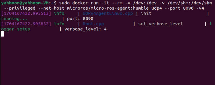
image-20240102115625254

Then, turn on the car switch and wait for the car to connect to the agent. The connection is successful, as shown in the figure below.
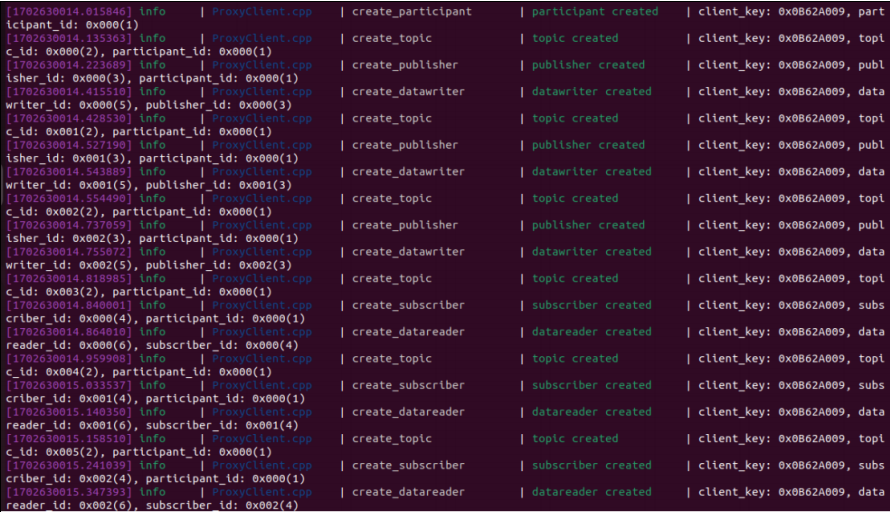
image-20231218095446172

3、starting program

First, start the car's underlying data processing program. This program will release the TF transformation of odom->base_footprint. With this TF change, you can calculate "how far the car has gone" and input it at the terminal.

xxxxxxxxxx
ros2 launch yahboomcar_bringup yahboomcar_bringup_launch.py
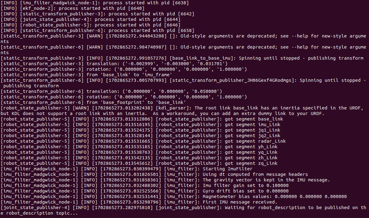
image-20231218100815056

Then, start the car linear speed calibration program and enter in the terminal,

xxxxxxxxxx
ros2 run yahboomcar_bringup calibrate_linear
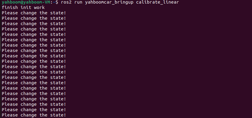
image-20231218100954839

Finally, open the dynamic parameter adjuster and enter in the terminal,

xxxxxxxxxx
ros2 run rqt_reconfigure rqt_reconfigure
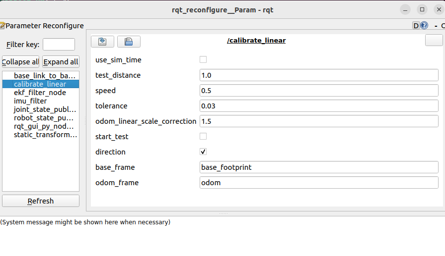
image-20231218102635972

Note: There may not be the above nodes when you first open it. You can see all nodes after clicking Refresh. The displayed calibrate_linear node is the node for calibrating linear speed.

4、Start calibration

In the rqt_reconfigure interface, select the calibrate_linear node. There is start_test below and click the box to the right to start calibration. Other parameters in the rqt interface are explained as follows:

  • test_distance:Calibrate the test distance, here the test goes forward 1 meter;

  • speed:Linear speed;

  • tolerance:tolerance for error;

  • odom_linear_scale_correction:Linear speed proportional coefficient, if the test result is not ideal, just modify this value;

  • start_test:test switch:

  • direction:It can be ignored. This value is used for the wheel structure trolley. After modification, the linear speed of left and right movement can be calibrated;

  • base_frame:The name of the base coordinate system;

  • odom_frame:The name of the odometer coordinate system.

Click start_test to start calibration. The car will monitor the TF transformation of base_footprint and odom, calculate the theoretical distance traveled by the car, wait until the error is less than the tolerance, and issue a parking instruction.
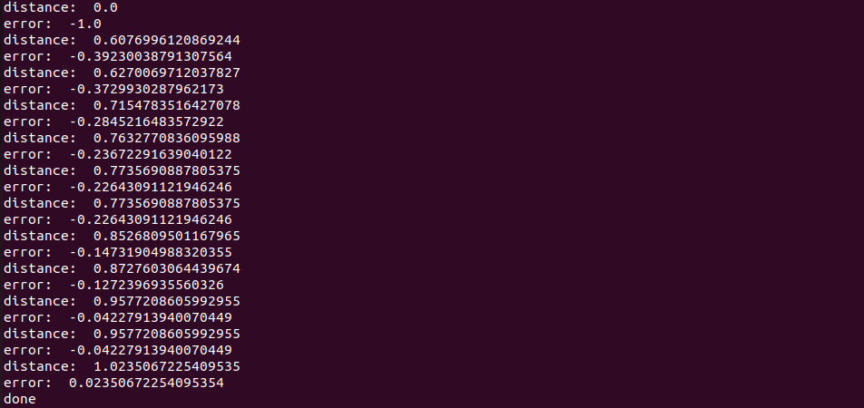
image-20231218104407056

If the actual distance the car runs is not 1m, then modify the odom_linear_scale_correction parameter in rqt. After modification, click on the blank space, click start_test again, reset start_test, and then click start_test again to calibrate. The same goes for modifying other parameters. You need to click on the blank space to write the modified parameters.

5、Code analysis

Source code reference path (taking the supporting virtual machine as an example):

xxxxxxxxxx
/home/yahboom/yahboomcar_ws/src/yahboomcar_bringup/yahboomcar_bringup

calibrate_linear.py, the core code is as follows,

x
#Monitor the TF transformation of base_footprint and odom
def get_position(self):
    try:
        now = rclpy.time.Time()
        trans = self.tf_buffer.lookup_transform(self.odom_frame,self.base_frame,now)
        #print("trans: ",trans)   
        return trans       
    except (LookupException, ConnectivityException, ExtrapolationException):
        self.get_logger().info('transform not ready')
        raise
        return
#Get the current coordinates
self.position.x = self.get_position().transform.translation.x
self.position.y = self.get_position().transform.translation.y
#Calculate how far distance and error are
distance = sqrt(pow((self.position.x - self.x_start), 2) +pow((self.position.y - self.y_start), 2))
distance *= self.odom_linear_scale_correction
print("distance: ",distance)
error = distance - self.test_distance


Robot state estimation
Angular velocity calibration

COMPANY

  • About us
  • Team Style
  • Blog

LEARNING & EXPLORATION

  • Tutorials
  • Edge AI hardware
  • Educational robots
  • Embedded intelligent hardware

WHERE TO BUY

  • Yahboom Online Store
  • Amazon
  • Alibaba
  • AliExpress
  • Mercado

TECHNOLOGY SUPPORT

  • Email: support@yahboom.com

BE A DISTRIBUTOR

  • Email: sales@yahboom.com
QR Code
QR Code

Copyright © 2017-2026 Yahboom. All Rights Reserved.

EN/中文