Welcome to MicroROS Robot repository
8. Read motor encoder data
Read motor encoder data
1. Experimental purpose
Using the encoded motor interface of the microROS control board, learn how the ESP32 uses PCNT components to capture the number of motor encoder pulses.
2. Hardware connection
As shown in the figure below, the microROS control board integrates four encoder motor control interfaces. An additional encoder motor needs to be connected. The motor control interface supports 310 motors. A type-C data cable also needs to be connected to the computer and the microROS control board to burn firmware. Function.
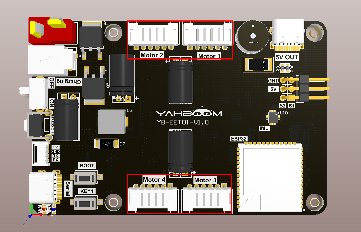
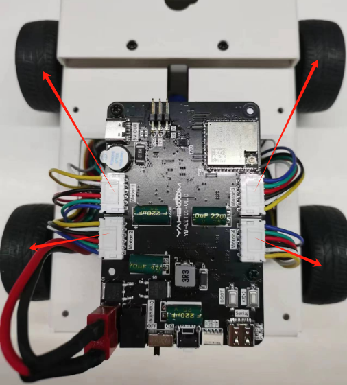
The corresponding names of the four motor interfaces are: left front wheel->Motor1, left rear wheel->Motor2, right front wheel->Motor3, right rear wheel->Motor4.
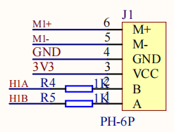
Motor interface line sequence, there is a detailed line sequence silk screen on the back of the microROS control board. Here we take Motor1 as an example. M1+ and M1- are the interfaces for controlling the rotation of the motor. GND and VCC are the power supply circuits of the encoder. H1A and H1B are the encoder pulses. Detection pin.
Note: If you are using the 310 motor and motor cable provided by Yabo Intelligence, connect the white wire shell end to the interface on the microROS control board, and the black wire shell end to the 310 motor interface.
3. Core code analysis
The virtual machine path corresponding to the program source code is as follows
~/esp/Samples/esp32_samples/encoder
Since the initialization process of four-way motors is similar, here we take the encoder initialization of motor 1 as an example.
First, initialize the GPIO H1A and H1B of Motor 1 as PCNT capture interfaces with a frequency of 25KHz. Select timer group 0 as the PWM output timer group of Motor 1.
xxxxxxxxxxstatic void Encoder_M1_Init(void){pcnt_unit_config_t unit_config = {.high_limit = ENCODER_PCNT_HIGH_LIMIT,.low_limit = ENCODER_PCNT_LOW_LIMIT,.flags.accum_count = true, // enable counter accumulation};pcnt_unit_handle_t pcnt_unit = NULL;ESP_ERROR_CHECK(pcnt_new_unit(&unit_config, &pcnt_unit));pcnt_glitch_filter_config_t filter_config = {.max_glitch_ns = 1000,};ESP_ERROR_CHECK(pcnt_unit_set_glitch_filter(pcnt_unit, &filter_config));pcnt_chan_config_t chan_a_config = {.edge_gpio_num = ENCODER_GPIO_H1A,.level_gpio_num = ENCODER_GPIO_H1B,};pcnt_channel_handle_t pcnt_chan_a = NULL;ESP_ERROR_CHECK(pcnt_new_channel(pcnt_unit, &chan_a_config, &pcnt_chan_a));pcnt_chan_config_t chan_b_config = {.edge_gpio_num = ENCODER_GPIO_H1B,.level_gpio_num = ENCODER_GPIO_H1A,};pcnt_channel_handle_t pcnt_chan_b = NULL;ESP_ERROR_CHECK(pcnt_new_channel(pcnt_unit, &chan_b_config, &pcnt_chan_b));ESP_ERROR_CHECK(pcnt_channel_set_edge_action(pcnt_chan_a, PCNT_CHANNEL_EDGE_ACTION_DECREASE, PCNT_CHANNEL_EDGE_ACTION_INCREASE));ESP_ERROR_CHECK(pcnt_channel_set_level_action(pcnt_chan_a, PCNT_CHANNEL_LEVEL_ACTION_KEEP, PCNT_CHANNEL_LEVEL_ACTION_INVERSE));ESP_ERROR_CHECK(pcnt_channel_set_edge_action(pcnt_chan_b, PCNT_CHANNEL_EDGE_ACTION_INCREASE, PCNT_CHANNEL_EDGE_ACTION_DECREASE));ESP_ERROR_CHECK(pcnt_channel_set_level_action(pcnt_chan_b, PCNT_CHANNEL_LEVEL_ACTION_KEEP, PCNT_CHANNEL_LEVEL_ACTION_INVERSE));ESP_ERROR_CHECK(pcnt_unit_add_watch_point(pcnt_unit, ENCODER_PCNT_HIGH_LIMIT));ESP_ERROR_CHECK(pcnt_unit_add_watch_point(pcnt_unit, ENCODER_PCNT_LOW_LIMIT));ESP_ERROR_CHECK(pcnt_unit_enable(pcnt_unit));ESP_ERROR_CHECK(pcnt_unit_clear_count(pcnt_unit));ESP_ERROR_CHECK(pcnt_unit_start(pcnt_unit));encoder_unit_m1 = pcnt_unit;}
Read the accumulated number of encoder pulses of motor 1.
xxxxxxxxxxint Encoder_Get_Count_M1(void){static int count_m1 = 0;pcnt_unit_get_count(encoder_unit_m1, &count_m1);return count_m1;}
For the convenience of reading, the number of accumulated encoder pulses of the motor is obtained according to the ID number of the encoder.
xxxxxxxxxxint Encoder_Get_Count(uint8_t encoder_id){if (encoder_id == ENCODER_ID_M1) return Encoder_Get_Count_M1();if (encoder_id == ENCODER_ID_M2) return Encoder_Get_Count_M2();if (encoder_id == ENCODER_ID_M3) return Encoder_Get_Count_M3();if (encoder_id == ENCODER_ID_M4) return Encoder_Get_Count_M4();return 0;}
Call the Encoder_Init function in app_main to initialize the motor encoder, and print the accumulated pulse number of the four motor encoders every 200 milliseconds in the loop.
xvoid app_main(void){printf("hello yahboom\n");ESP_LOGI(TAG, "Nice to meet you!");Encoder_Init();vTaskDelay(pdMS_TO_TICKS(1000));while (1){ESP_LOGI(TAG, "Encoder:%d, %d, %d, %d",Encoder_Get_Count_M1(), Encoder_Get_Count_M2(),Encoder_Get_Count_M3(), Encoder_Get_Count_M4());vTaskDelay(pdMS_TO_TICKS(200));}}
4. Compile, download and flash firmware
Use a Type-C data cable to connect the virtual machine/computer and the microROS control board. If the system pops up, choose to connect to the virtual machine.
Activate the ESP-IDF development environment. Note that every time you open a new terminal, you need to activate the ESP-IDF development environment before compiling the firmware.
xxxxxxxxxxsource ~/esp/esp-idf/export.sh
Enter the project directory
xxxxxxxxxxcd ~/esp/Samples/esp32_samples/encoder
Compile, flash, and open the serial port simulator
xxxxxxxxxxidf.py build flash monitor
If you need to exit the serial port simulator, press Ctrl+].
5. Experimental results
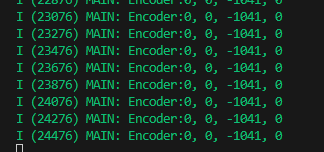
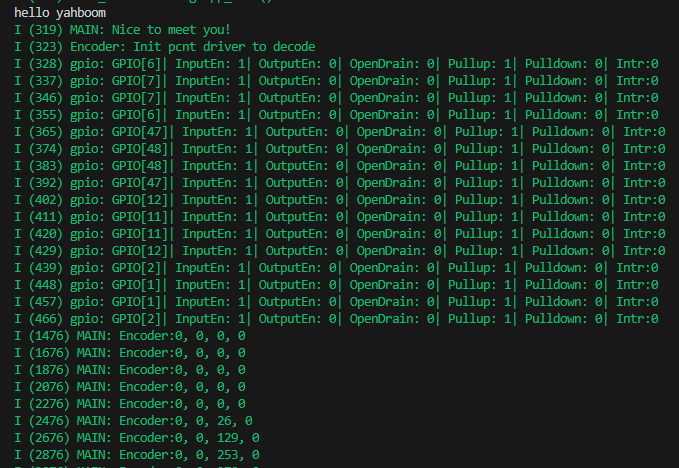
The serial port simulator prints the "hello yahboom" greeting. At this time, the pulse data of the four-channel motor encoder will be printed every 200 milliseconds. As shown in the figure below, the motor Motor3 is rotated, so the third data will change.
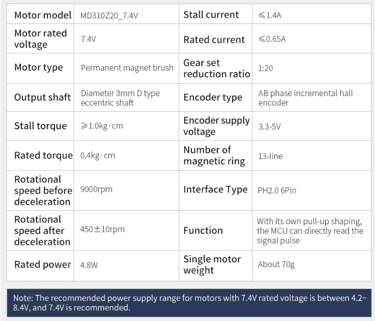
According to the parameters of the motor, the motor reduction ratio is 1:20, the encoder is a 13-line AB phase Hall encoder, and the software uses high and low level triggering at the same time, so the theoretical number of pulses for one revolution of the motor should be 1040.
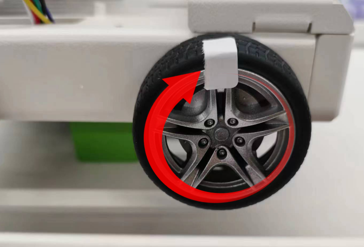
Taking rotating motor 3 as an example, when the wheel turns forward, the encoder data accumulates. When the wheel turns forward for one turn, the encoder data increases by approximately 1040. Since there is a certain error in manual rotation, there may be differences in the values, as long as the difference is not large.
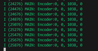
Press the reset button on the microROS control board to reset the value to 0.
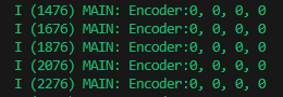
When the wheel turns backward, the encoder data decreases cumulatively. If it turns backward for one turn, it will decrease by approximately 1040.