Welcome to MicroROS Robot repository
1. Color tracking
Color tracking
Note: The VM and ROS-wifi image transfer module must be consistent with the microROS control board ROS_DOMAIN_ID and set the value to 20. You can check [MicroROS control board Parameter configuration] to set the microROS control board ROS_DOMAIN_ID. Check the tutorial Connecting to MicroROS Agents to see if the ids are the same.
Before running the experiment, make sure that the microros cart and ROS-wifi graph transfer module are properly enabled on the virtual machine (linux with humbleROS2 system)
1、Program function specification
MicroROS robot color tracking, with the ability to recognize a variety of colors at any time, and autonomously store the current recognized colors, control the car head to follow the detection of the recognized colors.
The color tracking of MicroROS robot can also realize the function of real-time regulation of HSV. By adjusting the high and low threshold of HSV, the interfered color can be filtered out, so that the square can be recognized in a complex environment very ideally. If the effect in color selection is not ideal, it is necessary to move the car to different environments for calibration. To be able to recognize the colors we need in a complex environment.
2、Program code reference path
~/yahboomcar_ws/src/yahboom_esp32ai_car/yahboom_esp32ai_car/colorHSV.py~/yahboomcar_ws/src/yahboom_esp32ai_car/yahboom_esp32ai_car/colorTracker.py
colorHSV.py
It is mainly to complete the image processing and calculate the central coordinates of the tracked object.
colorTracker.py
It is mainly based on the center coordinates and depth information of the tracked object to calculate the steering gear motion Angle data to the chassis.
3、Program initiation
3.1、Start command
enter the terminal,
x#Start the steering gear calibration procedure#When the Angle of the steering gear is not in the middle, the following commands need to be executedros2 run yahboom_esp32_mediapipe control_servo
# After the steering gear is moved, the steering gear is still not in the middle, and it is necessary to manually reinstall the head, which can be continuously operated by electricity, so that the steering gear is in a locked state for easy adjustmentAfter the steering gear is in the middle, press "Ctrl+C" to terminate the program to avoid affecting the next experimental operation
xxxxxxxxxx#Start the color trackerros2 run yahboom_esp32ai_car colorHSVros2 run yahboom_esp32ai_car colorTrackerIf the camera picture appears upside down,Need to see 3. Camera picture correction (must see) document itself correction, the experiment is no longer described.
Take tracking red as an example, after the program starts, the following screen will appear,
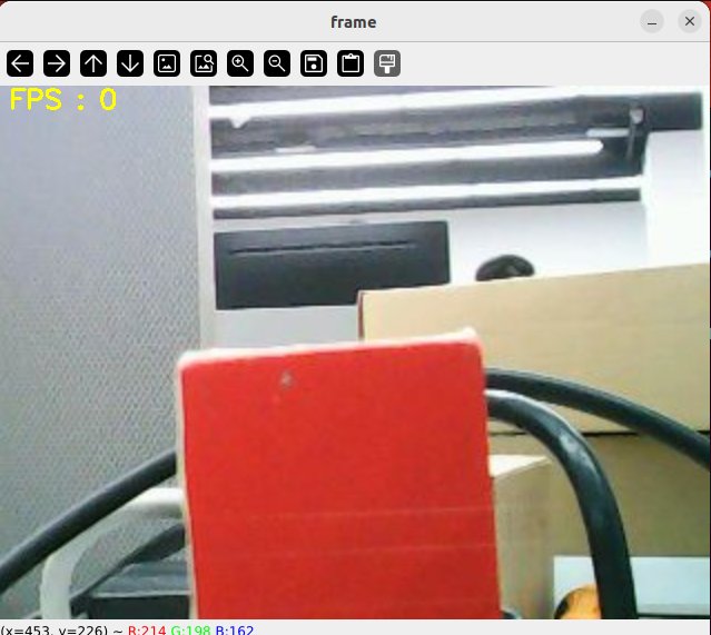
Then press the r/R key on the keyboard to enter the color selection mode, and frame an area with the mouse (the area can only have one color),
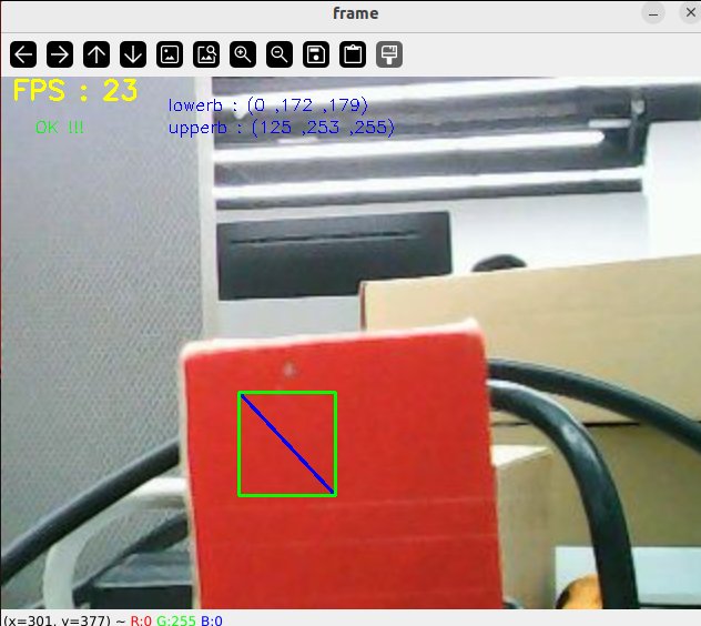
After selection, the effect is shown below,
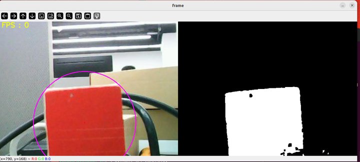
Then, press the space bar to enter the tracking mode, move the object slowly, and you can see that the robot head will track the color block movement.
3.2、Dynamic parameter regulation
terminal input,
xxxxxxxxxxros2 run rqt_reconfigure rqt_reconfigure
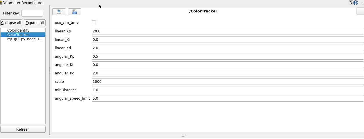
After modifying the parameters, click the blank area of the GUI to write the parameter value. As can be seen from the figure above,
- colorTracker The main adjustment PID three parameters to make the head more sensitive.
4、Core code
4.1、colorHSV.py
This program mainly has the following functions:
- Turn on the camera and get the image;
- Gets keyboard and mouse events for switching modes and fetching colors;
- Process the image and publish the center coordinates of the tracking object and publish it.
Some of the core code is as follows,
xxxxxxxxxx#Create a publisher that publishes the center coordinates of the tracking objectself.pub_position = self.create_publisher(Position,"/Current_point", 10)#Get the keyboard and mouse events, get the value of hsv; if action == 32: self.Track_state = 'tracking' elif action == ord('i') or action == ord('I'): self.Track_state = "identify" elif action == ord('r') or action == ord('R'): self.Reset() elif action == ord('q') or action == ord('Q'): self.cancel() if self.Track_state == 'init': cv.namedWindow(self.windows_name, cv.WINDOW_AUTOSIZE) cv.setMouseCallback(self.windows_name, self.onMouse, 0) if self.select_flags == True: cv.line(rgb_img, self.cols, self.rows, (255, 0, 0), 2) cv.rectangle(rgb_img, self.cols, self.rows, (0, 255, 0), 2) if self.Roi_init[0] != self.Roi_init[2] and self.Roi_init[1] != self.Roi_init[3]: rgb_img, self.hsv_range = self.color.Roi_hsv(rgb_img, self.Roi_init) self.gTracker_state = True self.dyn_update = True else: self.Track_state = 'init'#Calculate the value of the center coordinate, self.circle stores the xy valuergb_img, binary, self.circle = self.color.object_follow(rgb_img, self.hsv_range)#Publishes a message for the center coordinatesthreading.Thread(target=self.execute, args=(self.circle[0], self.circle[1], self.circle[2])).start()def execute(self, x, y, z): position = Position() position.anglex = x * 1.0 position.angley = y * 1.0 position.distance = z * 1.0 self.pub_position.publish(position)4.2、colorTracker.py
This program mainly has the following functions: receive /Current_point and depth image topic data, calculate the speed size, and then publish the speed data.
Part of the code is as follows,
xxxxxxxxxx
self.sub_depth = self.create_subscription(Image,"/image_raw", self.depth_img_Callback, 1)self.sub_JoyState =self.create_subscription(Bool,'/JoyState',self.JoyStateCallback,1)self.sub_position =self.create_subscription(Position,"/Current_point",self.positionCallback,1)
self.pub_cmdVel = self.create_publisher(Twist,'/cmd_vel',10)self.pub_Servo1 = self.create_publisher(Int32,"servo_s1" , 10)self.pub_Servo2 = self.create_publisher(Int32,"servo_s2" , 10)

def positionCallback(self, msg):def depth_img_Callback(self, msg):
self.execute(self.Center_x, distance_) def execute(self, point_x, point_y):        [x_Pid, y_Pid] = self.linear_pid .update([point_x - 320, point_y - 240])        if self.img_flip == True:            self.PWMServo_X += x_Pid            self.PWMServo_Y += y_Pid        else:            self.PWMServo_X  -= x_Pid            self.PWMServo_Y  += y_Pid
        if self.PWMServo_X  >= 45:            self.PWMServo_X  = 45        elif self.PWMServo_X  <= -45:            self.PWMServo_X  = -45        if self.PWMServo_Y >= 40:            self.PWMServo_Y = 40        elif self.PWMServo_Y <= -90:            self.PWMServo_Y = -90
        # rospy.loginfo("target_servox: {}, target_servoy: {}".format(self.target_servox, self.target_servoy))        print("servo1",self.PWMServo_X)        servo1_angle = Int32()        servo1_angle.data = int(self.PWMServo_X)        servo2_angle = Int32()        servo2_angle.data = int(self.PWMServo_Y)        self.pub_Servo1.publish(servo1_angle)        self.pub_Servo2.publish(servo2_angle)