yahboom
HomeLearn
Solution
Blog
Online Store
About Us
EN/中文
PALMSLAM📖
1. Product Introduction
  • 0.Get started
  • 1. Learning route
  • 2. Frequently Questions
  • 3. Control panel introduction
  • 4. Introduction to LiDAR
  • 5. Robot charging and battery considerations
  • 6.Unboxing and reviewing
2. Assembly video
  • Installation Video
3. Basic configuration
  • 0. Get started quickly
  • 1. Write the firmware
  • 2. Virtual machine installation and startup system
  • 3. Expansion board configuration parameters
  • 4. How to choose the alarm level and radar model
  • 5. Connection Agent
4. LiDAR course
  • 0. Enter the same docker terminal
  • 1. Robot information release
  • 2. Robot URDF model
  • 3. Basic distance measurement function
  • 4. SLAM Gmapping
  • 5. SLAM Cartographer
  • 6. APP mapping
5. Linux operating system
  • 1.Introduction to Linux system
  • 2.Ubuntu file system
  • 3.Ubuntu common commands
  • 4.Ubuntu common editors
  • 5.Ubuntu software operation commands
  • 6.Virtual machine installation
  • 7.SSH remote control
  • 8.VNC remote control
  • 9.Transfer files remotely
  • 10.Driver library and communication
  • 11.Static IP and hotspot mode
  • 12.Bind device ID
  • 13.Capacity expansion and resource allocation
  • 14.Update system software sources
  • 15.Set root user password
  • 16.sudo free password
  • 17.Connect to WiFi network
  • 18.View system version
  • 19.Customized service management
  • 20.Back up system image
6. ROS2 Basic Course
  • 1.Introduction to ROS2
  • 2.ROS2 install Humble
  • 3.ROS2 development environment
  • 4.ROS2 workspace
  • 5.ROS2 function package
  • 6.ROS2 node
  • 7.ROS2 topic communication
  • 8.ROS2 service communication
  • 9.ROS2 action communication
  • 10.ROS2 custom interface message
  • 11.ROS2 parameter service case
  • 12.ROS2 meta-function package
  • 13.ROS2 distributed communication
  • 14.ROS2 DDS
  • 15.ROS2 time related API
  • 16.ROS2 common command tools
  • 17.ROS2 rviz2 use
  • 18.ROS2 rqt toolbox
  • 19.ROS2 Launch startup file configuration
  • 20.ROS2 recording and playback tool
  • 21.ROS2 URDF model
  • 22.ROS2 Gazebo simulation platform
  • 23.ROS2 TF2 coordinate transformation
Download
  • System_File
  • VM_File
  • Code
  • Software_Tool
  • Hareware_Info
  • 3D_Model_File
  • Instruction_Manual
  • ROS2_Basic_VM
Download ZIP

Welcome to PALMSLAM repository

3. Control panel introduction

Introduction to the control board

The control board is a lightweight ROS2 driver controller and an ESP32S3 dual-core development board. The board integrates important peripherals such as the ESP32S3 core module control unit and the six-axis IMU attitude sensor, supports serial communication, and comes with a peripheral driver firmware program. Users can directly access the ROS2 environment for use, which is convenient to operate, simple and efficient to use.

Description of onboard resources
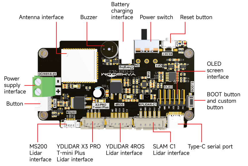
img

Power supply interface: Connect a 7.4V battery (T-type interface) to power the robot.

Battery charging interface: Connect a DC8.4V charger to charge the robot.

Power switch: The main power switch of the robot.

Reset button: The reset button of the ESP32S3 control chip.

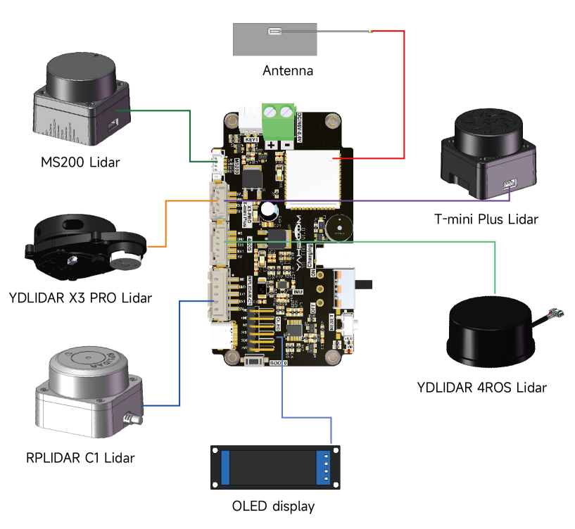
MS200 radar interface: Connect the MS200 laser radar.

X3/Tminiplus radar interface: Connect the X3/Tminiplus radar.

4ROS radar interface: Connect the 4ROS laser radar.

Silan C1 radar interface: connect to C1 laser radar.

Type-C serial port: used for burning firmware, configuring parameters, serial communication and other functions.

Power indicator and MCU indicator: indicate the current status of the product.

BOOT button: BOOT button of ESP32S3 control chip, custom button can also be used.

Custom button: GPIO of ESP32S3 control chip, programmable custom function.

OLED screen interface: OLED driver interface

Antenna interface: connect external antenna.

Buzzer: active buzzer, used for low voltage alarm prompt.

KEY1 button interface: select radar model, warning level and other functions

GPIO pin assignment
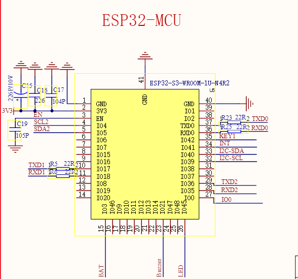
image-20241125115034476

Peripheral nameESP32-S3-GPIO
OELD-SCLGPIO4
OELD-SDAGPIO5
BOOT button-IO0GPIO0
Custom button-KEY1GPIO42
Battery voltage detection-BATGPIO3
MCU indicator-LEDGPIO45
Buzzer-BuzzerGPIO46
IMU interrupt-INTGPIO41
IMU-I2C-SCLGPIO39
IMU-I2C-SDAGPIO40
Radar RX-Serial Port 1-TXD1GPIO17
Radar TX-Serial Port 1-RXD1GPIO18
TypeC Burning Serial Port RX-TXD0GPIO43
TypeC Burning Serial Port TX-RXD0GPIO44

Expansion Board Wiring Diagram

image-20241125115548874

Frequently Questions
Introduction to LiDAR

COMPANY

  • About us
  • Team Style
  • Blog

LEARNING & EXPLORATION

  • Tutorials
  • Edge AI hardware
  • Educational robots
  • Embedded intelligent hardware

WHERE TO BUY

  • Yahboom Online Store
  • Amazon
  • Alibaba
  • AliExpress
  • Mercado

TECHNOLOGY SUPPORT

  • Email: support@yahboom.com

BE A DISTRIBUTOR

  • Email: sales@yahboom.com
QR Code
QR Code

Copyright © 2017-2026 Yahboom. All Rights Reserved.

EN/中文