Welcome to RDK X3 Board repository
1. Using GPIO
1. Using GPIO
1. Using GPIO1. Import GPIO libaray2. Set pin encoding mode3. Warning message4. Pin configuration5. Input operation6. Output operation7. Clean up pin occupation8. Check pin status9. Edge detection and interruptwait_for_edge() functionevent_detected() functionRun callback function when edge event is detectedDisable interrupts10. Test routine
1. Import GPIO libaray
The development board comes with a pre-installed GPIO Python library Hobot.GPIO. Users can import the GPIO library using the following command.
xxxxxxxxxxsunrise@ubuntu:~$ sudo python3Python 3.8.10 (default, Mar 15 2022, 12:22:08) Type "help", "copyright", "credits" or "license" for more information.>>> import Hobot.GPIO as GPIOGet board ID: 0x504>>> GPIO.VERSION'0.0.2'>>> GPIO.model'X3PI'2. Set pin encoding mode
There are 4 modes for the pin coding of the development board.
- BOARD: physical pin number, corresponding to the silkscreen number of the development board.
- BCM: GPIO naming rules formulated according to Broadcom SoC.
- CVM: Use strings instead of numbers, corresponding to the signal names of the CVM/CVB connector.
- SOC: The corresponding number is the GPIO pin number of the X3M chip, which corresponds to the chip data sheet.
This article recommends that users use the BOARD coding mode, and the coding method is as follows.
xxxxxxxxxxGPIO.setmode(GPIO.BOARD)# orGPIO.setmode(GPIO.BCM)# orGPIO.setmode(GPIO.CVM)# or GPIO.setmode(GPIO.SOC)Query encoding method.
xxxxxxxxxxmode = GPIO.getmode()The program will output one of the results: BOARD, BCM, CVM, SOC or None.
3. Warning message
When running the code in the following cases, there will be warning log output, but it will not affect normal functions.
- The GPIO that the user is trying to use has been used in other applications;
- Before setting the mode and channel, try to call
GPIO.cleanupto clean up the pin;
If you want to block the warning message, you can use the following command.
xxxxxxxxxxGPIO.setwarnings(False)4. Pin configuration
Before using the GPIO pin, you need to configure it accordingly, as follows.
The way to set it as input is as follows.
xxxxxxxxxxGPIO.setup(channel, GPIO.IN)The way to set it to output is as follows.
xxxxxxxxxxGPIO.setup(channel, GPIO.OUT)You can also specify an initial value for the output channel, for example.
xxxxxxxxxxGPIO.setup(channel, GPIO.OUT, initial=GPIO.HIGH)In addition, the tool supports setting multiple output channels at the same time, for example.
xxxxxxxxxx# set gpio(18,12,13) to outputchannels = [18, 12, 13]GPIO.setup(channels, GPIO.OUT)5. Input operation
To read the value of a channel:
xxxxxxxxxxGPIO.input(channel)The command return value is 0 or 1.
0 represents GPIO.LOW, 1 represents GPIO.HIGH.
6. Output operation
To set the output value of a channel.
xxxxxxxxxxGPIO.output(channel, state)State can be GPIO.LOW or GPIO.HIGH.
7. Clean up pin occupation
Before exiting the program, you can clean up the channel.
xxxxxxxxxxGPIO.cleanup()If you want to clean only a specific channel, use the following command.
x
# Clear a single channelGPIO.cleanup(channel)# Clear a group of channelsGPIO.cleanup( (channel1, channel2) )GPIO.cleanup( [channel1, channel2] )8. Check pin status
This function allows you to check the functionality of the corresponding GPIO channel.
xxxxxxxxxxGPIO.gpio_function(channel)该函数返回 IN 或 OUT。
9. Edge detection and interrupt
An edge is a change in an electrical signal from low to high (rising edge) or from high to low (falling edge). This change can be regarded as an event that can be used to trigger a CPU interrupt signal.
The GPIO library provides three methods to detect input events.
wait_for_edge() function
This function blocks the calling thread until the corresponding edge change is detected.
The function call is as follows.
xxxxxxxxxxGPIO.wait_for_edge(channel, GPIO.RISING)The second parameter specifies the edge to detect, and the value range is GPIO.RISING, GPIO.FALLING, or GPIO.BOTH.
If you want to specify a waiting time, you can choose to set a timeout.
x
# Timeout in millisecondsGPIO.wait_for_edge(channel, GPIO.RISING, timeout=500)If the external signal changes within the timeout period, the function returns the detected channel number.
If a timeout occurs, the function returns None.
event_detected() function
This function can be used to periodically check if any events have occurred since the last call.
This function can be set and called as follows.
x
# Set up rising edge detection on channel GPIOGPIO.add_event_detect(channel, GPIO.RISING)if GPIO.event_detected(channel): print("Rising edge event detected")You can detect events of GPIO.RISING, GPIO.FALLING, or GPIO.BOTH.
Run callback function when edge event is detected
This function can be used to register callback function, which runs in an independent processing thread.
The instructions are as follows.
xxxxxxxxxx# define callback functiondef callback_fn(channel):    print("Callback called from channel %s" % channel)
# enable rising detectionGPIO.add_event_detect(channel, GPIO.RISING, callback=callback_fn)
If necessary, you can also add multiple callbacks, as follows.
xxxxxxxxxxdef callback_one(channel):    print("First Callback")
def callback_two(channel):    print("Second Callback")
GPIO.add_event_detect(channel, GPIO.RISING)GPIO.add_event_callback(channel, callback_one)GPIO.add_event_callback(channel, callback_two)
Since all callbacks run on the same thread, different callbacks are run sequentially, not simultaneously.
To prevent callbacks from being called multiple times by combining multiple events into one, you can optionally set a debounce time.
xxxxxxxxxx# bouncetime unit is msGPIO.add_event_detect(channel, GPIO.RISING, callback=callback_fn, bouncetime=200)Disable interrupts
If edge detection is no longer needed, it can be removed, as follows.
xxxxxxxxxxGPIO.remove_event_detect(channel)10. Test routine
The main test routines are provided in the /app/40pin_samples/ directory.
| Test routine name | Explanation |
|---|---|
| simple_out.py | Single pin output test |
| simple_input.py | Single pin input test |
| button_led.py | One pin is used as a key input, and one pin is used as an output to control the LED |
| test_all_pins_input.py | Input test code for all pins |
| test_all_pins.py | Output test code for all pins |
| button_event.py | Capture the rising and falling edge events of the pin |
| button_interrupt.py | Interrupt mode to handle rising and falling edge events of the pin |
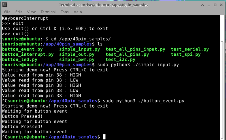
As shown in the figure, take running simple_input.py and button_event.py as an example.
GPIO is set to
output mode, and the output level is switched every 1 second. It can be used to control the LED light to turn on and off in a cycle.Test code
simple_out.py
xxxxxxxxxx#!/usr/bin/env python3
import Hobot.GPIO as GPIOimport time
# Define the GPIO channel used as 38output_pin = 38 # BOARD Coding 38
def main():    # Set the pin encoding mode to hardware encoding BOARD    GPIO.setmode(GPIO.BOARD)    # Set to output mode and initialize to high level    GPIO.setup(output_pin, GPIO.OUT, initial=GPIO.HIGH)    # Record the current pin status    curr_value = GPIO.HIGH    print("Starting demo now! Press CTRL+C to exit")    try:        # 1 second interval, cycle control LED light on and off        while True:            time.sleep(1)            GPIO.output(output_pin, curr_value)            curr_value ^= GPIO.HIGH    finally:        GPIO.cleanup()
if __name__=='__main__': main()- Set GPIO to
input modeand read the pin level value through busy polling. Test codesimple_input.py.
x
#!/usr/bin/env python3
import Hobot.GPIO as GPIOimport time
# Define the GPIO channel used as 38input_pin = 38 # BOARD coding 38
def main(): prev_value = None
# Set the pin encoding mode to hardware encoding BOARD GPIO.setmode(GPIO.BOARD) # Set as input mode GPIO.setup(input_pin, GPIO.IN)
print("Starting demo now! Press CTRL+C to exit") try: while True: &nb