Welcome to RDK X3 Board repository
5. Using SPI
Using SPI
1. Loopback test
RDK X3 leads to the SPI2 bus of the X3M chip on the physical pins 19, 21, 23, 24 on 40Pin, supports one chip select, and the IO voltage is 3.3V.
RDK Ultra leads to the SPI0 bus on the physical pins 19, 21, 23, 24, 26 on 40Pin, supports two chip selects, and the IO voltage is 3.3V.
Please refer to /app/40pin_samples/test_spi.py for details on how to use SPI.
Connect MISO and MOSI on the hardware, then run the spi test program to perform write and read operations. The expected result is that the read data is exactly equal to the written data.
2. Hardware connection
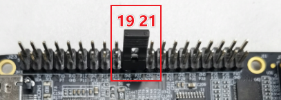
Connect MISO and MOSI together directly through the jumper cap
3. Test process
- Run
python3 /app/40pin_samples/test_spi.py - Select the bus number and chip select number from the printed spi controller as input options. For example, if you choose to test
spidev2.0, thebus numis 2, and thecs numis 0. Press Enter to confirm.
xxxxxxxxxxList of enabled spi controllers:/dev/spidev2.0 Please input SPI bus num:2Please input SPI cs num:0- When the program runs correctly, it will continuously print
0x55 0xAA. If it prints0x00 0x00, it means that the SPI loopback test has failed.
xxxxxxxxxxStarting demo now! Press CTRL+C to exit0x55 0xAA0x55 0xAA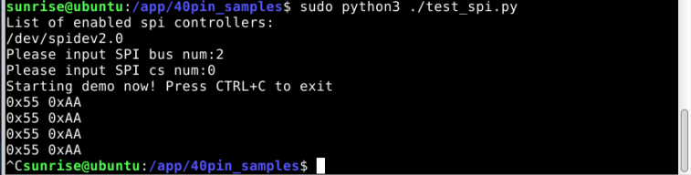
4. Test code
x
#!/usr/bin/env python3
from __future__ import print_functionimport sysimport osimport time
# Import spidev moduleimport spidev
def BytesToHex(Bytes): return ''.join(["0x%02X " % x for x in Bytes]).strip()
def spidevTest(): # Set the SPI bus number (0, 1, 2) and chip select (0, 1) spi_bus = input("Please input SPI bus num:") spi_device = input("Please input SPI cs num:") # Create an object of spidev class to access spidev based Python functions. spi=spidev.SpiDev() # Open the spi bus handle spi.open(int(spi_bus), int(spi_device))
# Set spi frequency to 12MHz spi.max_speed_hz = 12000000
print("Starting demo now! Press CTRL+C to exit")
# Send [0x55, 0xAA], receive should also be [0x55, 0xAA] try: while True: resp = spi.xfer2([0x55, 0xAA]) print(BytesToHex(resp)) time.sleep(1)