Welcome to MicroROS Robot Expansion Board repository
1. Introduction to microROS control board
Brief introduction of microROS control board
The MicroROS control board is a ROS2 driver controller and an ESP32S3 dual-core development board. On board ESP32S3 core module control unit, motor driver, servo driver, six-axis IMU attitude sensor and other important peripherals. It supports WiFi, Bluetooth, serial port and other communication functions, and supports 4-channel encoder motors, 2-channel PWM servos, 1-channel lidar and 1-channel ESP32 WiFi camera module, Type-C power interface supports Raspberry Pi 5(5.1V/5A) PD power supply protocol. And it comes with peripheral driver firmware, users can directly access the ROS2 environment for use.
Description of onboard resources
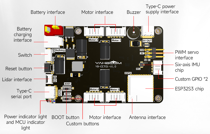
Battery power interface: connect 7.4V battery (T-type interface) to power the robot.
Battery charging interface: Connect DC8.4V charger to charge the robot.
Power switch: robot power main switch.
Reset button: The reset button of the ESP32S3 control chip.
Lidar interface: Connect the MS200 lidar.
Type-C serial port: used for burning firmware, configuration parameters, serial communication and other functions.
BOOT button: The BOOT button of the ESP32S3 control chip can also be used with custom keys.
Custom button: ESP32S3 control chip GPIO, programmable custom function.
Motor interface: Connect 310 encoder motor.
Antenna interface: Connect the external antenna.
ESP32S3 control chip: The main control chip of the microROS control board is responsible for managing all peripheral functions on the board.
Six-axis IMU chip: provides the current pose information of the robot.
Custom GPIO *2: UART port, can be used connect WiFi camera module.
PWM servo interface: used to connect two PWM servo.
Type-C Power supply interface: Connect the Type-C interface of the Raspberry PI 5 to power the Raspberry PI 5.
Buzzer: Active buzzer for low voltage alarm prompt.
Power indicator: red constant light means normal.
MCU indicator light: under normal circumstances, it will always flash in a cycle (the frequency is two flashes every three seconds); Flash at low voltage (every 100 ms); In configuration mode, it flashes slowly (once per second). In test mode, it will blink continuously (three flashes every three seconds).
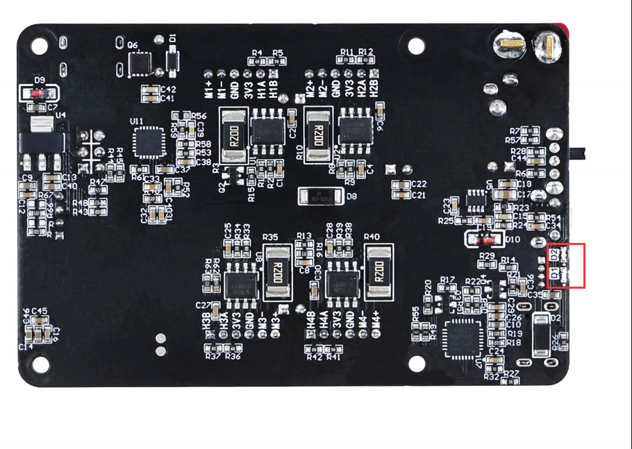
D1 and D2: Custom indicators.
GPIO Pin Assignment
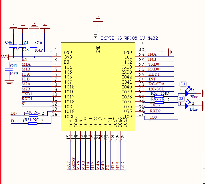
| Name of peripheral device | ESP32-S3-GPIO |
|---|---|
| Motor M1-PWM-M1A | GPIO4 |
| MotorM1-PWM-M1B | GPIO5 |
| MotorM1-encoder-H1A | GPIO6 |
| MotorM1-encoder-H1B | GPIO7 |
| MotorM2-PWM-M2A | GPIO15 |
| MotorM2-PWM-M2B | GPIO16 |
| MotorM2-encoder-H2A | GPIO47 |
| MotorM2-encoder-H2B | GPIO48 |
| MotorM3-PWM-M3A | GPIO9 |
| MotorM3-PWM-M3B | GPIO10 |
| MotorM3-encoder-H3A | GPIO11 |
| MotorM3-encoder-H3B | GPIO12 |
| MotorM4-PWM-M4A | GPIO13 |
| MotorM4-PWM-M4B | GPIO14 |
| MotorM4-encoder-H4A | GPIO1 |
| MotorM4-encoder-H4B | GPIO2 |
| BOOT button-IO0 | GPIO0 |
| Custom key-KEY1 | GPIO42 |
| Battery voltage detection-BAT | GPIO3 |
| MCU indicator light-LED | GPIO45 |
| Buzzer | GPIO46 |
| Servo interface -S1 | GPIO8 |
| Servo interface -S2 | GPIO21 |
| IMU interrupts -INT | GPIO41 |
| IMU-I2C-SCL | GPIO39 |
| IMU-I2C-SDA | GPIO40 |
| Radar RX-serial port 1-TXD1 | GPIO17 |
| Radar TX-serial port 1-RXD1 | GPIO18 |
| Type-C serial port RX-TXD0 | GPIO43 |
| Type-C serial port TX-RXD0 | GPIO44 |
| Custom GPIO | GPIO35 |
| Custom GPIO | GPIO36 |
| Custom indicator lights | D1 |
| Custom indicator lights | D2 |