Welcome to MicroROS Robot Expansion Board repository
6. Drive PWM servo
Drive PWM servo
Drive PWM servo1. Experimental purpose2. Hardware connection3. Core code analysis4. Compile, download and flash firmware5. Experimental results
1. Experimental purpose
Use the PWM output of the microROS control board to learn how ESP32 controls the PWM servo.
2. Hardware connection
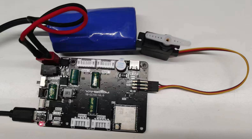
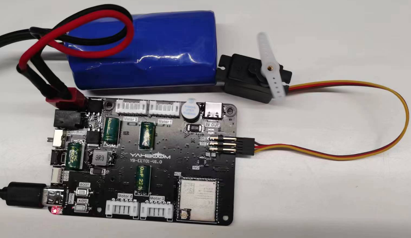
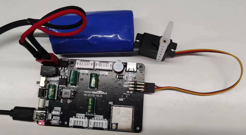
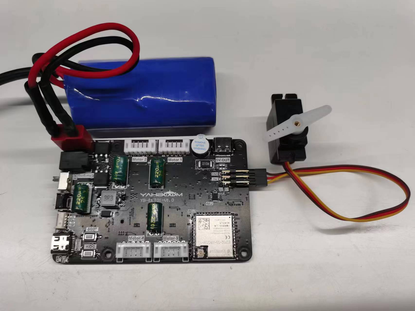
As shown in the figure below, the microROS control board integrates the PWM servo control interface, but requires an additional connection to the PWM servo. The PWM servo needs to be prepared by yourself. You also need to connect the type-C data cable to the computer and the microROS control board as a firmware flash function.
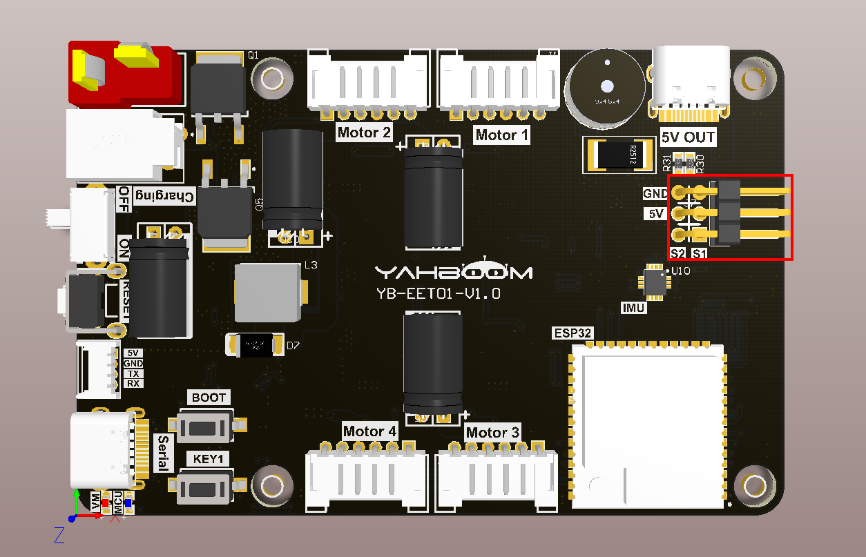
The bottom of the PWM servo port is S1, and the top is S2. Please connect according to the silk screen. The brown wire is connected to GND, the red wire is connected to 5V, and the yellow wire is connected to S1/S2.
3. Core code analysis
The virtual machine path corresponding to the program source code is as follows
~/esp/Samples/esp32_samples/pwm_servo
Since the initialization methods of servos S1 and S2 are not much different, the only difference is that servo S1 corresponds to hardware GPIO8 and servo S2 corresponds to hardware GPIO21. The following explanation takes servo S1 as an example.
First, initialize the GPIO of servo S1 to PWM output with a frequency of 50HZ, and use timer group 1 as the PWM output clock.
xxxxxxxxxxstatic void Servo_S1_Init(void){mcpwm_timer_handle_t timer = NULL;mcpwm_timer_config_t timer_config = {.group_id = SERVO_TIMER_GROUP_ID,.clk_src = MCPWM_TIMER_CLK_SRC_DEFAULT,.resolution_hz = SERVO_TIMEBASE_RESOLUTION_HZ,.period_ticks = SERVO_TIMEBASE_PERIOD,.count_mode = MCPWM_TIMER_COUNT_MODE_UP,};ESP_ERROR_CHECK(mcpwm_new_timer(&timer_config, &timer));mcpwm_oper_handle_t oper = NULL;mcpwm_operator_config_t operator_config = {.group_id = SERVO_TIMER_GROUP_ID, // operator must be in the same group to the timer};ESP_ERROR_CHECK(mcpwm_new_operator(&operator_config, &oper));ESP_ERROR_CHECK(mcpwm_operator_connect_timer(oper, timer));mcpwm_comparator_config_t comparator_config = {.flags.update_cmp_on_tez = true,};ESP_ERROR_CHECK(mcpwm_new_comparator(oper, &comparator_config, &comparator_S1));mcpwm_gen_handle_t generator = NULL;mcpwm_generator_config_t generator_config = {.gen_gpio_num = SERVO_GPIO_S1,};ESP_ERROR_CHECK(mcpwm_new_generator(oper, &generator_config, &generator));uint32_t cmp1 = Servo_S1_Angle_To_Compare(SERVO_S1_DEF_ANGLE);ESP_ERROR_CHECK(mcpwm_comparator_set_compare_value(comparator_S1, cmp1));ESP_ERROR_CHECK(mcpwm_generator_set_action_on_timer_event(generator,MCPWM_GEN_TIMER_EVENT_ACTION(MCPWM_TIMER_DIRECTION_UP, MCPWM_TIMER_EVENT_EMPTY, MCPWM_GEN_ACTION_HIGH)));ESP_ERROR_CHECK(mcpwm_generator_set_action_on_compare_event(generator,MCPWM_GEN_COMPARE_EVENT_ACTION(MCPWM_TIMER_DIRECTION_UP, comparator_S1, MCPWM_GEN_ACTION_LOW)));ESP_ERROR_CHECK(mcpwm_timer_enable(timer));ESP_ERROR_CHECK(mcpwm_timer_start_stop(timer, MCPWM_TIMER_START_NO_STOP));}
Convert the input angle of the servo S1 into the PWM duty cycle value.
xxxxxxxxxxstatic uint32_t Servo_S1_Angle_To_Compare(int8_t angle){if (angle > SERVO_S1_MAX_ANGLE) angle = SERVO_S1_MAX_ANGLE;if (angle < SERVO_S1_MIN_ANGLE) angle = SERVO_S1_MIN_ANGLE;int cmp = ((int)angle - SERVO_MIN_HD_ANGLE) * (SERVO_MAX_PULSEWIDTH_US - SERVO_MIN_PULSEWIDTH_US) / (SERVO_MAX_HD_ANGLE - SERVO_MIN_HD_ANGLE) + SERVO_MIN_PULSEWIDTH_US;return (uint32_t)cmp;}
Among them, the maximum and minimum values of the servo pulse, and the maximum and minimum values of the servo control range, according to the PWM servo control characteristics, just keep the following values unchanged.
xxxxxxxxxx#define SERVO_MIN_PULSEWIDTH_US 500 // Minimum pulse width in microsecond#define SERVO_MAX_PULSEWIDTH_US 2500 // Maximum pulse width in microsecond#define SERVO_MIN_HD_ANGLE -90 // Minimum Angle of Servo#define SERVO_MAX_HD_ANGLE 90 // Maximum Angle of Servo
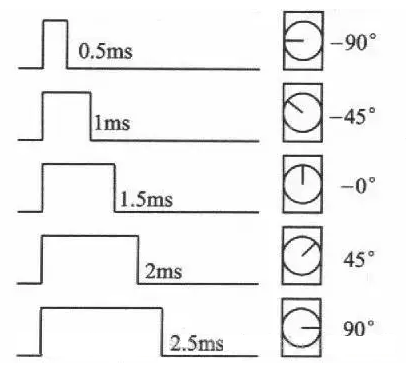
To control the servo angle, the control can be distinguished according to the input servo ID, and then the angle value is converted into a PWM duty cycle pulse value and transmitted to the mcpwm module of ESP32, thereby outputting square waves with different duty cycles to drive the servo to rotate.
xxxxxxxxxxvoid Servo_Set_Angle(servo_id_t servo_id, int8_t angle){int8_t angle_servo = 0;if (servo_id == SERVO_ID_S1){angle_servo = -angle;ESP_ERROR_CHECK(mcpwm_comparator_set_compare_value(comparator_S1, Servo_S1_Angle_To_Compare(angle_servo)));return;}if (servo_id == SERVO_ID_S2){angle_servo = angle;ESP_ERROR_CHECK(mcpwm_comparator_set_compare_value(comparator_S2, Servo_S2_Angle_To_Compare(angle_servo)));return;}}
Note: In order to adapt to the servo gimbal, the control angle of the gimbal has been restricted. If you want to cancel the restriction, please modify the content of the servo.h file to configure the servo angle.
x#define SERVO_S1_DEF_ANGLE (0) // Default angle of S1#define SERVO_S1_MIN_ANGLE (-90) // Limit the minimum angle of S1#define SERVO_S1_MAX_ANGLE (90) // Limit the maximum angle of S1#define SERVO_S2_DEF_ANGLE (-60) // Default angle of S2#define SERVO_S2_MIN_ANGLE (-90) // Limit the minimum angle of S2#define SERVO_S2_MAX_ANGLE (20) // Limit the maximum angle of S2
Call the Servo_Init function in app_main to initialize the servo, and then change the angle of the servo S1 every 1000 milliseconds in the loop to achieve the back-and-forth swing of the servo.
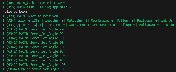
xxxxxxxxxxvoid app_main(void){printf("hello yahboom\n");ESP_LOGI(TAG, "Nice to meet you!");Servo_Init();vTaskDelay(pdMS_TO_TICKS(1000));while (1){ESP_LOGI(TAG, "Servo_Set_Angle:-90");Servo_Set_Angle(SERVO_ID_S1, -90);vTaskDelay(pdMS_TO_TICKS(1000));ESP_LOGI(TAG, "Servo_Set_Angle:90");Servo_Set_Angle(SERVO_ID_S1, 90);vTaskDelay(pdMS_TO_TICKS(1000));}}
4. Compile, download and flash firmware
Use a Type-C data cable to connect the virtual machine/computer and the microROS control board. If the system pops up, choose to connect to the virtual machine.
Activate the ESP-IDF development environment. Note that every time you open a new terminal, you need to activate the ESP-IDF development environment before compiling the firmware.
xxxxxxxxxxsource ~/esp/esp-idf/export.sh
Enter the project directory
xxxxxxxxxxcd ~/esp/Samples/esp32_samples/pwm_servo
Compile, flash, and open the serial port simulator
xidf.py build flash monitor
If you need to exit the serial port simulator, press Ctrl+].
5. Experimental results
The serial port simulator prints the "hello yahboom" greeting. And the angle of the servo S1 is changed every second, from -90 to 90, and then from 90 to -90, and continues to run, thereby realizing the function of repeated rotation of the servo.