Welcome to MicroROS Robot Expansion Board repository
11. Read radar data
Read radar data
Read radar data1. Experimental purpose2. Hardware connection3. Core code analysis4. Compile and download the burning firmware5. Experimental results
1. Experimental purpose
Use the radar interface of the microROS control board to learn ESP32 to read the MS200 lidar data through serial port 1 and parse the radar data packets.
2. Hardware connection
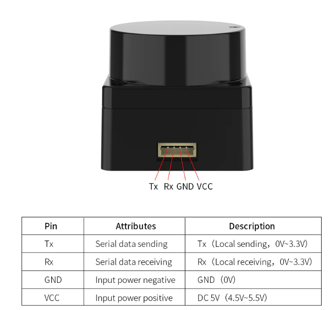
As shown in the figure below, the microROS control board integrates the MS200 lidar interface. You need to connect the MS200 lidar cable to the microROS control board and lidar. You also need to connect the type-C data cable to the computer and the microROS control board as a burning Firmware features.
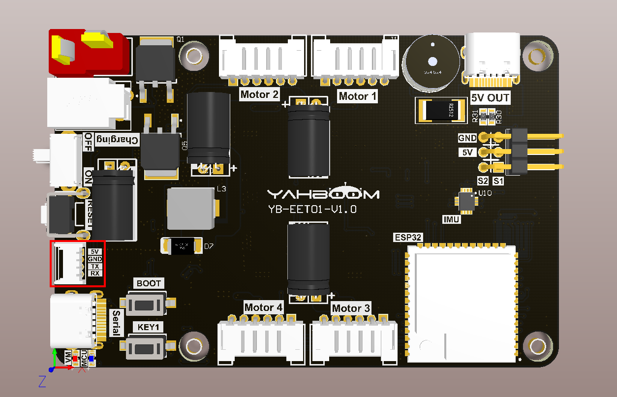
The MS200 lidar interface cable has an anti-reverse connection function and can be inserted directly into the interface.
3. Core code analysis
The virtual machine path corresponding to the program source code is as follows
~/esp/Samples/esp32_samples/read_lidar
Since the MS200 lidar uses serial port communication, serial port 1 of ESP32S3 is selected to communicate with the MS200 lidar. UART1_GPIO_TXD of serial port 1 corresponds to hardware GPIO17, UART1_GPIO_RXD of serial port 1 corresponds to hardware GPIO18, and the baud rate is set to 230400.
xvoid Uart1_Init(void){const uart_config_t uart_config = {.baud_rate = 230400,.data_bits = UART_DATA_8_BITS,.parity = UART_PARITY_DISABLE,.stop_bits = UART_STOP_BITS_1,.flow_ctrl = UART_HW_FLOWCTRL_DISABLE,.source_clk = UART_SCLK_DEFAULT,};uart_driver_install(UART_NUM_1, RX1_BUF_SIZE * 2, 0, 0, NULL, 0);uart_param_config(UART_NUM_1, &uart_config);uart_set_pin(UART_NUM_1, UART1_GPIO_TXD, UART1_GPIO_RXD, UART_PIN_NO_CHANGE, UART_PIN_NO_CHANGE);RingBuffer_Init(&uart1_ringbuf, RX1_BUF_SIZE);xTaskCreate(Uart1_Rx_Task, "Uart1_Rx_Task", 5*1024, NULL, configMAX_PRIORITIES, NULL);}
MS200 lidar analyzes system messages.
xxxxxxxxxxstatic void Ms200_Parse_Report(uint8_t* protocol_buf){int i;uint8_t data_len = protocol_buf[3];uint8_t crc8 = protocol_buf[data_len+4];if(protocol_buf[data_len+5] != MS200_TAIL_1 || protocol_buf[data_len+6] != MS200_TAIL_2) return;if (crc8 != Ms200_Calculate_CRC8(protocol_buf, data_len+4)){YB_DEBUG(TAG, "CRC8 Check Error");return;}// 判断SN码标志位,并保存SN码信息// Determine the SN flag bit and save the SN informationif(protocol_buf[2] == MS200_FLAG_SN){for (i = 0; i < data_len; i++){ms200_sn[i] = protocol_buf[4 + i];}ESP_LOGI(TAG, "SN:%s", ms200_sn);}// 判断版本标志位,并保存版本信息// Determine the version flag bit and save the version informationelse if (protocol_buf[2] == MS200_FLAG_VERSION){for (i = 1; i < data_len; i++){ms200_version[i-1] = protocol_buf[4 + i];}ESP_LOGI(TAG, "%s", ms200_version);}}
MS200 lidar parses point cloud data packets based on the received protocol data.
xxxxxxxxxxstatic int Ms200_Parse_Package(uint8_t* protocol_buf, ms200_package_t* out_pkg){uint8_t buf_len = (protocol_buf[1] & 0x1F) * 3 + 11;uint8_t check_num = protocol_buf[buf_len-1];uint8_t crc8 = Ms200_Calculate_CRC8(protocol_buf, buf_len-1);if (crc8 != check_num){YB_DEBUG(TAG, "CRC Error:%d, %d", crc8, check_num);return ESP_FAIL;}out_pkg->header = protocol_buf[0];out_pkg->count = protocol_buf[1] & 0x1F;out_pkg->speed = (protocol_buf[3] << 8) | protocol_buf[2];out_pkg->start_angle = (protocol_buf[5] << 8) | protocol_buf[4];out_pkg->end_angle = (protocol_buf[buf_len-4] << 8) | protocol_buf[buf_len-5];out_pkg->time_stamp = (protocol_buf[buf_len-2] << 8) | protocol_buf[buf_len-3];out_pkg->crc8 = protocol_buf[buf_len-1];for (int i = 0; i < MS200_POINT_PER_PACK; i++){out_pkg->points[i].distance = (protocol_buf[3*i+7] << 8) | protocol_buf[3*i+6];out_pkg->points[i].intensity = protocol_buf[3*i+8];}return ESP_OK;}
According to the point cloud data package, the relevant angle data is extracted. Special processing is added here. When the scanning angle passes from before 360 degrees to after 0 degrees, the angle value needs to be converted.
xxxxxxxxxxstatic void Ms200_Update_Data(ms200_package_t* pkg, ms200_data_t* out_data){uint16_t step_angle = 0;uint16_t angle = 0;if (pkg->end_angle > pkg->start_angle){// 正常情况 normal coditionstep_angle = (pkg->end_angle - pkg->start_angle) / (pkg->count - 1);}else{// 特殊情况(0度):结束角度小于开始角度// Special case: The end Angle is smaller than the start Anglestep_angle = (36000 + pkg->end_angle - pkg->start_angle) / (pkg->count - 1);}for (int i = 0; i < pkg->count; i++){angle = ((pkg->start_angle + i * step_angle) / 100) % MS200_POINT_MAX;out_data->points[angle].distance = pkg->points[i].distance;out_data->points[angle].intensity = pkg->points[i].intensity;}}
Get data from MS200 lidar.
xxxxxxxxxxvoid Ms200_Get_Data(ms200_data_t* out_data){*out_data = ms200_data;}
Create a new task of MS200 lidar analysis data and extraction of radar data.
xxxxxxxxxxstatic void Lidar_Ms200_Task(void *arg){ESP_LOGI(TAG, "Start Lidar_Ms200_Task with core:%d", xPortGetCoreID());uint16_t rx_count = 0;while (1){rx_count = Uart1_Available();if (rx_count){// Uart1_Clean_Buffer();for (int i = 0; i < rx_count; i++){Ms200_Data_Receive(Uart1_Read());}}if (Ms200_New_Package()){Ms200_Clear_New_Package_State();Ms200_Get_Data(&lidar_data);}else{vTaskDelay(pdMS_TO_TICKS(1));}}vTaskDelete(NULL);}
Read the distance detected by the MS200 lidar at a certain point, in millimeters.
xxxxxxxxxxuint16_t Lidar_Ms200_Get_Distance(uint16_t point){if (point < MS200_POINT_MAX){return lidar_data.points[point].distance;}return 0;}
In app_main, call the Uart1_Init function to initialize serial port 1 and Lidar_Ms200_Init to initialize the lidar. Then, in the loop, read the distances of the MS200 lidar in the four directions of 0 degrees, 90 degrees, 180 degrees, and 270 degrees every 200 milliseconds, and print them out.
xxxxxxxxxxvoid app_main(void){printf("hello yahboom\n");ESP_LOGI(TAG, "Nice to meet you!");Uart1_Init();Lidar_Ms200_Init();vTaskDelay(pdMS_TO_TICKS(1000));uint16_t points[4] = {0, 90, 180, 270};uint16_t distances[4] = {0};while (1){for (int i = 0; i < 4; i++){distances[i] = Lidar_Ms200_Get_Distance(points[i]);}ESP_LOGI(TAG, "distance:%d, %d, %d, %d", distances[0], distances[1], distances[2], distances[3]);vTaskDelay(pdMS_TO_TICKS(200));}}
4. Compile and download the burning firmware
Use a Type-C data cable to connect the virtual machine/computer and the microROS control board. If the system pops up, choose to connect to the virtual machine.
Activate the ESP-IDF development environment. Note that every time you open a new terminal, you need to activate the ESP-IDF development environment before compiling the firmware.
xxxxxxxxxxsource ~/esp/esp-idf/export.sh
Enter the project directory
xxxxxxxxxxcd ~/esp/Samples/esp32_samples/read_lidar
Compile, flash, and open the serial port simulator
xxxxxxxxxxidf.py build flash monitor
If you need to exit the serial port simulator, press Ctrl+].
5. Experimental results
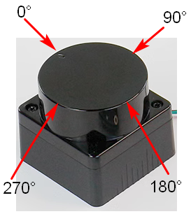
The serial port simulator prints the "hello yahboom" greeting. And every 200 milliseconds, the distance detected by the MS200 lidar in four directions of 0 degrees, 90 degrees, 180 degrees, and 270 degrees is printed. Among them, the direction indicated by the MS200 lidar arrow is 0 degrees, and the angle increases clockwise. At this time, you can block one of the directions with your hand and observe its numerical changes.