Welcome to MicroROS Robot Expansion Board repository
12. Flash access data
Flash access data
Flash access data1. Experimental purpose2. Hardware connection3. Core code analysis4. Compile, download and flash firmware5. Experimental results
1. Experimental purpose
Use the flash storage function of the microROS control board to learn the data saving function of ESP32 when it is powered off.
2. Hardware connection
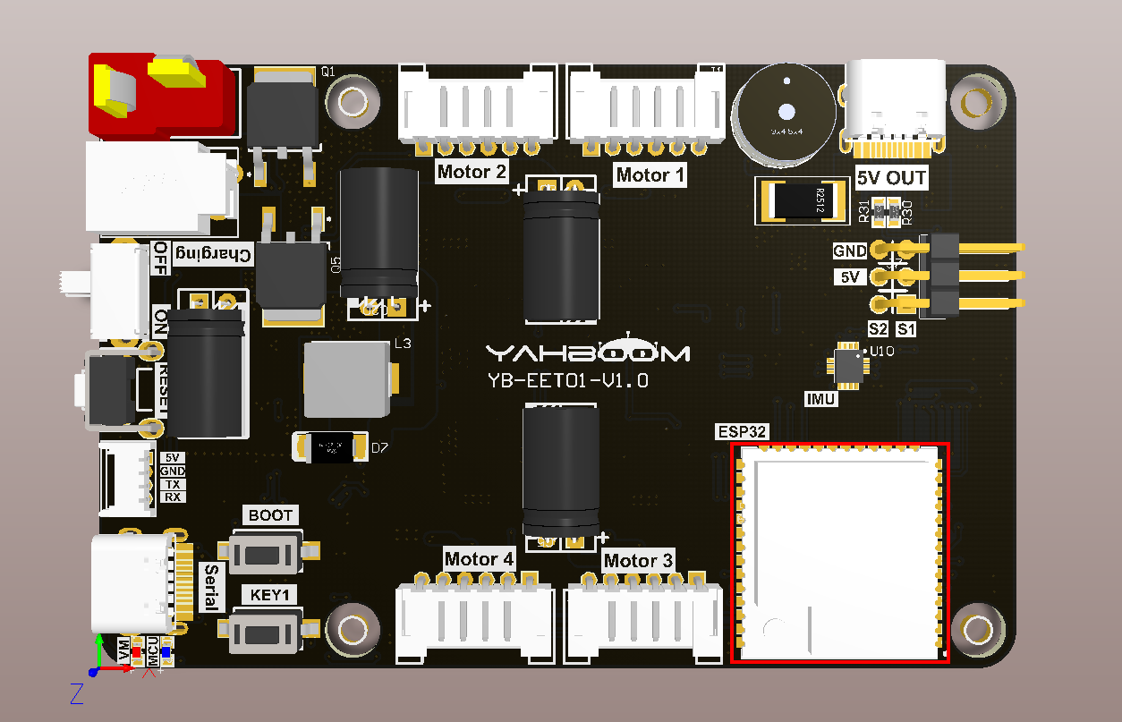
As shown in the figure below, the microROS control board integrates the ESP32-S3-WROOM-1U-N4R2 core module. It not only has internal space, but also has an additional 4MB FLASH program space and 2MB PSRAM memory space. You only need to connect the type-C data cable Connect the computer to the microROS control board as a firmware burning function.
3. Core code analysis
The virtual machine path corresponding to the program source code is:
~/esp/Samples/esp32_samples/flash
Initialize the flash chip. Since the pins of the flash chip have been reserved internally in ESP32-S3, there is no need to separately configure the pins of the flash chip when using the ESP32-S3-WROOM core module.
xxxxxxxxxxvoid Flash_Init(void){// Initialize NVSesp_err_t err = nvs_flash_init();if (err == ESP_ERR_NVS_NO_FREE_PAGES || err == ESP_ERR_NVS_NEW_VERSION_FOUND){// NVS partition was truncated and needs to be erased// Retry nvs_flash_initESP_ERROR_CHECK(nvs_flash_erase());err = nvs_flash_init();}ESP_ERROR_CHECK(err);}
There are many types of flash chip access, and different keys are used to distinguish different data locations. Here we take reading an int32 type of data from flash as an example.
xxxxxxxxxxesp_err_t Flash_Read_Data_Int32(const char* key, int32_t* out_value){nvs_handle_t my_handle;int32_t read_value = 0;esp_err_t err = ESP_OK;err = nvs_open(STORAGE_NAMESPACE, NVS_READONLY, &my_handle);if (err != ESP_OK) return err;err = nvs_get_i32(my_handle, key, &read_value);if (err == ESP_OK){*out_value = read_value;}else{*out_value = 0;}nvs_close(my_handle);return err;}
Write an int32 type data to the flash chip.
xxxxxxxxxxesp_err_t Flash_Write_Data_Int32(const char* key, int32_t value){nvs_handle_t my_handle;esp_err_t err = ESP_FAIL;int32_t read_value = 0;err = nvs_open(STORAGE_NAMESPACE, NVS_READWRITE, &my_handle);if (err != ESP_OK) return err;err = nvs_set_i32(my_handle, key, value);// 写入数据后必须调用nvs_commit提交写入闪存。// After writing data, you must call nvs commit to write to flash.if (err == ESP_OK) err = nvs_commit(my_handle);if (err == ESP_OK) err = nvs_get_i32(my_handle, key, &read_value);if (err == ESP_OK && value != read_value) err = ESP_FAIL;YB_DEBUG(TAG, "%s %d, Write int32:%ld, Read:%ld", key, err, value, read_value);nvs_close(my_handle);return err;}
Read a uint16 data from the flash chip.
xxxxxxxxxxesp_err_t Flash_Read_Data_UInt16(const char* key, uint16_t* out_value){nvs_handle_t my_handle;uint16_t read_value = 0;esp_err_t err = ESP_OK;err = nvs_open(STORAGE_NAMESPACE, NVS_READONLY, &my_handle);if (err != ESP_OK) return err;err = nvs_get_u16(my_handle, key, &read_value);if (err == ESP_OK){*out_value = read_value;}else{*out_value = 0;}nvs_close(my_handle);return err;}
Write a uint16 data to the flash chip.
xesp_err_t Flash_Write_Data_UInt16(const char* key, uint16_t value){nvs_handle_t my_handle;esp_err_t err = ESP_FAIL;uint16_t read_value = 0;err = nvs_open(STORAGE_NAMESPACE, NVS_READWRITE, &my_handle);if (err != ESP_OK) return err;err = nvs_set_u16(my_handle, key, value);// 写入数据后必须调用nvs_commit提交写入闪存。// After writing data, you must call nvs commit to write to flash.if (err == ESP_OK) err = nvs_commit(my_handle);if (err == ESP_OK) err = nvs_get_u16(my_handle, key, &read_value);if (err == ESP_OK && value != read_value) err = ESP_FAIL;YB_DEBUG(TAG, "%s %d, Write u16:%d, Read:%d", key, err, value, read_value);nvs_close(my_handle);return err;}
Read a piece of data from the flash chip.
xxxxxxxxxxesp_err_t Flash_Read_Blob(const char* key, char* out_data, uint16_t* length){nvs_handle_t my_handle;esp_err_t err = ESP_OK;size_t read_length = *length;err = nvs_open(STORAGE_NAMESPACE, NVS_READONLY, &my_handle);if (err != ESP_OK) return err;err = nvs_get_blob(my_handle, key, out_data, &read_length);*length = read_length;nvs_close(my_handle);YB_DEBUG(TAG, "%s %d, Read:%s, len:%d", key, err, out_data, read_length);return err;}
Write a piece of data to the flash chip.
xxxxxxxxxxesp_err_t Flash_Write_Blob(const char* key, char* in_data, uint16_t length){nvs_handle_t my_handle;esp_err_t err = ESP_OK;size_t write_length = length;err = nvs_open(STORAGE_NAMESPACE, NVS_READWRITE, &my_handle);if (err != ESP_OK) return err;err = nvs_set_blob(my_handle, key, in_data, write_length);// 写入数据后必须调用nvs_commit提交写入闪存。// After writing data, you must call nvs commit to write to flash.if (err == ESP_OK) err = nvs_commit(my_handle);YB_DEBUG(TAG, "%s %d, Write:%s, len:%d", key, err, in_data, write_length);nvs_close(my_handle);return err;}
In order to distinguish the area where flash stores data, the following different FKEYs are defined to distinguish different data.
xxxxxxxxxx#define FKEY_TEST_INT32 "TEST_INT32"#define FKEY_TEST_UINT16 "TEST_UINT16"#define FKEY_TEST_BLOB "TEST_BLOB"
For ease of use, add the key component key to the flash project, and then modify the value stored in the flash by reading the status of the key.
xxxxxxxxxxvoid app_main(void){printf("hello yahboom\n");ESP_LOGI(TAG, "Nice to meet you!");vTaskDelay(pdMS_TO_TICKS(100));Key_Init();Flash_Init();uint16_t value_u16 = 0;int32_t value_i32 = 0;uint16_t blob_len = 20;char* test_blob = malloc(blob_len);// 将数据从flash中读取出来,并打印输出。// Read the data from flash and print it out.Flash_Read_Data_UInt16(FKEY_TEST_UINT16, &value_u16);ESP_LOGI(TAG, "read u16 value: %d", value_u16);Flash_Read_Data_Int32(FKEY_TEST_INT32, &value_i32);ESP_LOGI(TAG, "read i32 value: %ld", value_i32);Flash_Read_Blob(FKEY_TEST_BLOB, (char*)test_blob, &blob_len);ESP_LOGI(TAG, "read blob: %s", test_blob);while (1){if (Key0_Read_State() == KEY_STATE_PRESS){ESP_LOGI(TAG, "KEY 0 PRESS");value_u16++;Flash_Write_Data_UInt16(FKEY_TEST_UINT16, value_u16);ESP_LOGI(TAG, "save u16 value: %d", value_u16);}if (Key1_Read_State() == KEY_STATE_PRESS){ESP_LOGI(TAG, "KEY 1 PRESS");value_i32++;sprintf(test_blob, "blob:%ld", value_i32);Flash_Write_Data_Int32(FKEY_TEST_INT32, value_i32);Flash_Write_Blob(FKEY_TEST_BLOB, test_blob, blob_len);ESP_LOGI(TAG, "save flash blob: %s", test_blob);}vTaskDelay(pdMS_TO_TICKS(10));}}
4. Compile, download and flash firmware
Use a Type-C data cable to connect the virtual machine/computer and the microROS control board. If the system pops up, choose to connect to the virtual machine.
Activate the ESP-IDF development environment. Note that every time you open a new terminal, you need to activate the ESP-IDF development environment before compiling the firmware.
xxxxxxxxxxsource ~/esp/esp-idf/export.sh
Enter the project directory
xxxxxxxxxxcd ~/esp/Samples/esp32_samples/flash
Compile, flash, and open the serial port simulator
xxxxxxxxxxidf.py build flash monitor
If you need to exit the serial port simulator, press Ctrl+]。
5. Experimental results
The serial port simulator prints the "hello yahboom" greeting. Since the blob in the flash is read for the first time as unconfirmed data, after the program is burned for the first time, the read blob line reads garbled characters. You only need to press the KEY1 key to refresh the blob data in the flash, and the next time you turn on the computer No garbled characters will be read.
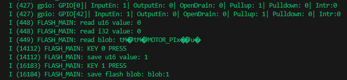
At this time, you can press the BOOT button, and the saved u16 value will increase. If you press the KEY1 key, the saved blob value will increase.
After pressing the reset key, the currently written data is read.
