yahboom
HomeLearn
Solution
Blog
Online Store
About Us
EN/中文
MicroROS Robot Expansion Board📖
01. microROS control board development environment
  • 1. Introduction to microROS control board
  • 2. Set up ESP32-IDF development environment
  • 3. ESP32-IDF configuration tool
  • 4. Install ESP32-microros components
  • 5. Install and start microROS agent
  • 6. Flash-tool burning firmware
02. ESP32 basic course
  • 1. Turn on the LED light
  • 2. Button function
  • 3. Drive the buzzer
  • 4. Serial communication
  • 5. Battery voltage detection
  • 6. Drive PWM servo
  • 7. Drive motor
  • 8. Read motor encoder data
  • 9. PID controls car speed
  • 10. Read IMU data
  • 11. Read radar data
  • 12. Flash access data
  • 13. Partition table and memory
  • 14. Bluetooth communication
  • 15. WiFi networking
  • 16. Robot kinematics analysis
  • 17.Drive ESP32 WiFi camera
03. microros basic course
  • 1.Publish topic
  • 2. Subscribe topic
  • 3. Multi-topic subscribe and publish
  • 4. Subscribe buzzer topics
  • 5. Subscribe PWM servo topics
  • 6. Subscribe speed control topics
  • 7. Release speed topic
  • 8. Release IMU data topic
  • 9. Publish lidar data topics
  • 10. Customized transmission method
04.ROS2 basic course
  • 1. Introduction to ROS2
  • 2.ROS2 install Humble
  • 3.ROS2 development environment
  • 4.ROS2 workspace
  • 5.ROS2 function package
  • 6.ROS2 node
  • 7.ROS2 topic communication
  • 8.ROS2 service communication
  • 9.ROS2 action communication
  • 10.ROS2 custom interface message
  • 11.ROS2 parameter service case
  • 12.ROS2 meta-function package
  • 13.ROS2 distributed communication
  • 14.ROS2 DDS
  • 15.ROS2 time related API
  • 16.ROS2 common command tools
  • 17.ROS2 rviz2 use
  • 18.ROS2 rqt toolbox
  • 19.ROS2 Launch startup file configuration
  • 20.ROS2 recording and playback tool
  • 21.ROS2 URDF model
  • 22.ROS2 Gazebo simulation platform
  • 23.ROS2 TF2 coordinate transformation
05. Robot basic course
4.1 Robot information release
  • Robot information release
4.0 Preparation
  • 1. Write firmware
  • 2. How to install and use VM
  • 3. microROS control board configuration
  • 4. Connect to microROS agent
4.2 Robot keyboard control
  • Robot keyboard control
4.3 Robot handle control
  • Robot handle control
4.4 Robot state estimation
  • Robot state estimation
4.5 Line speed calibration
  • Line speed calibration
4.6 Angular velocity calibration
  • Angular velocity calibration
4.7 Robot URDF model
  • Robot URDF model
Download
  • Firmware And Code
  • VM_File
  • 3D Model File
  • ROS2_Basic_VM
Download ZIP

Welcome to MicroROS Robot Expansion Board repository

13. Partition table and memory

Partition table and memory

Partition table and memory1. Experimental purpose2. Hardware connection3. Core code analysis4. Compile, download and flash firmware5. Experimental results

1. Experimental purpose

Use the ESP32S3 core module of the microROS control board to learn the function of ESP32 custom partition table.


2. Hardware connection

As shown in the figure below, the microROS control board integrates the ESP32-S3-WROOM-1U-N4R2 core module. It not only has internal space, but also has an additional 4MB FLASH program space and 2MB PSRAM memory space. You only need to connect the type-C data cable Connect the computer to the microROS control board as a firmware burning function.
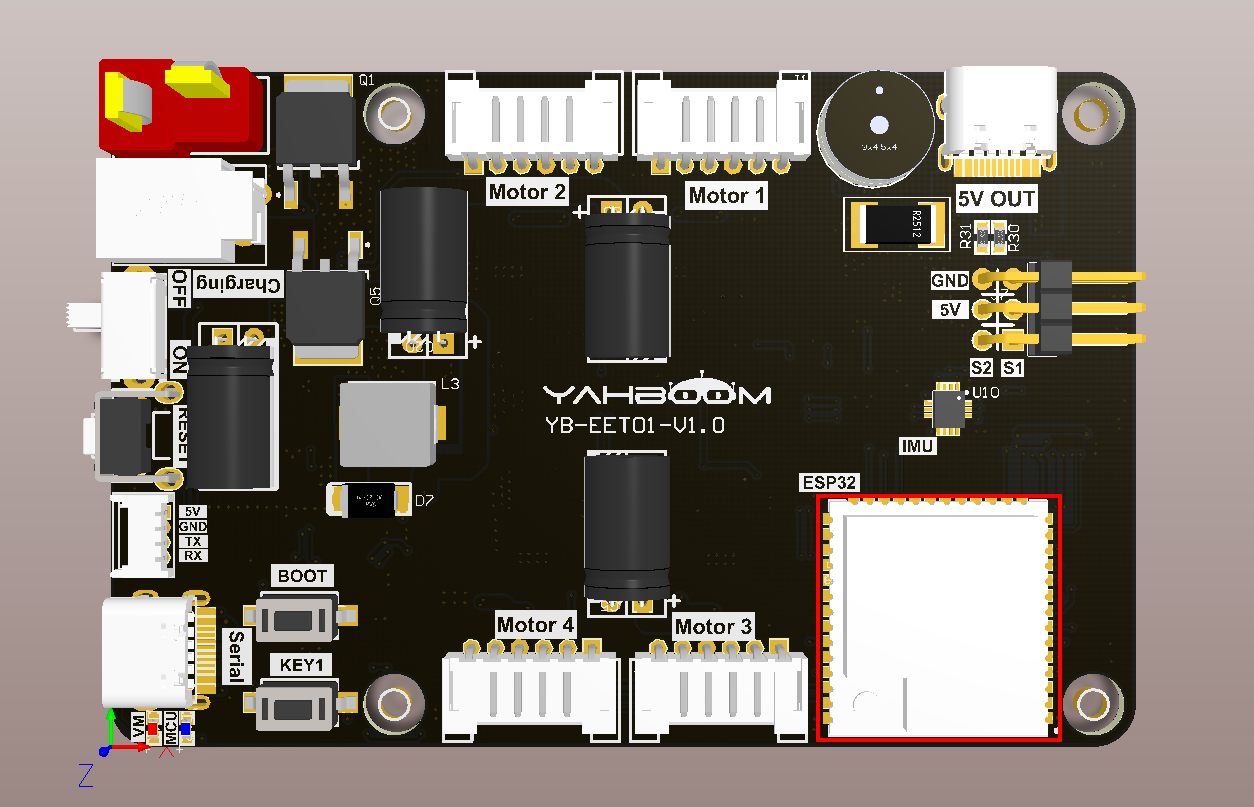
image-20240112174901940


3. Core code analysis

The virtual machine path corresponding to the program source code is as follows

~/esp/Samples/esp32_samples/partition_table

Create a new partitions.csv file in the project root directory and add the following content.

xxxxxxxxxx
# Name,   Type, SubType, Offset,  Size,   Flags
# Note: if you have increased the bootloader size, make sure to update the offsets to avoid overlap
nvs,      data, nvs,     0x9000,  0x6000,
phy_init, data, phy,     0xf000,  0x1000,
factory,  app,  factory, 0x10000, 3M,

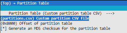
Then open the IDF configuration tool and specify the partition table as partitions.csv.
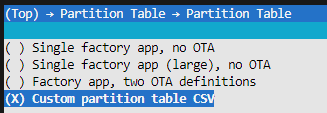
image-20240115105903174

image-20240115105930619


4. Compile, download and flash firmware

Use a Type-C data cable to connect the virtual machine/computer and the microROS control board. If the system pops up, choose to connect to the virtual machine.

Activate the ESP-IDF development environment. Note that every time you open a new terminal, you need to activate the ESP-IDF development environment before compiling the firmware.

xxxxxxxxxx
source ~/esp/esp-idf/export.sh

Enter the project directory

xxxxxxxxxx
cd ~/esp/Samples/esp32_samples/partition_table

Compile project

xxxxxxxxxx
idf.py build

You can see that the partition table printed during compilation is consistent with the partitions.csv file.
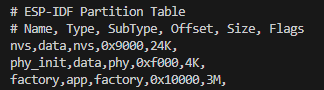
image-20240115110522843

Flash and open the serial port simulator

xxxxxxxxxx
idf.py flash monitor

If you need to exit the serial port simulator, press Ctrl+].


5. Experimental results

The serial port simulator prints the "hello yahboom" greeting.

image-20240115112425843

Then slide the mouse wheel upward to view the printed system information. You can see the partition table content displayed in the boot: Partition Table column, which is consistent with the content of partitions.csv in the project root directory.

image-20240115112531589


Flash access data
Bluetooth communication

COMPANY

  • About us
  • Team Style
  • Blog

LEARNING & EXPLORATION

  • Tutorials
  • Edge AI hardware
  • Educational robots
  • Embedded intelligent hardware

WHERE TO BUY

  • Yahboom Online Store
  • Amazon
  • Alibaba
  • AliExpress
  • Mercado

TECHNOLOGY SUPPORT

  • Email: support@yahboom.com

BE A DISTRIBUTOR

  • Email: sales@yahboom.com
QR Code

Copyright © 2017-2026 Yahboom. All Rights Reserved.

EN/中文