Welcome to MicroROS Robot Expansion Board repository
Robot URDF model
Robot URDF model
Note: The virtual machine needs to be in the same LAN as the car, and the ROS_DOMAIN_ID needs to be consistent. You can check [Must read before use] to set the IP and ROS_DOMAIN_ID on the board.
1、Program function description
The car connects to the agent, runs the program, and the URDF model will be displayed in rviz.
2、Program start
Load URDF and generate a simulation controller, terminal input,
ros2 launch yahboomcar_description display_launch.pyOpen rivz to display the model and enter in the terminal,
xxxxxxxxxxrviz2
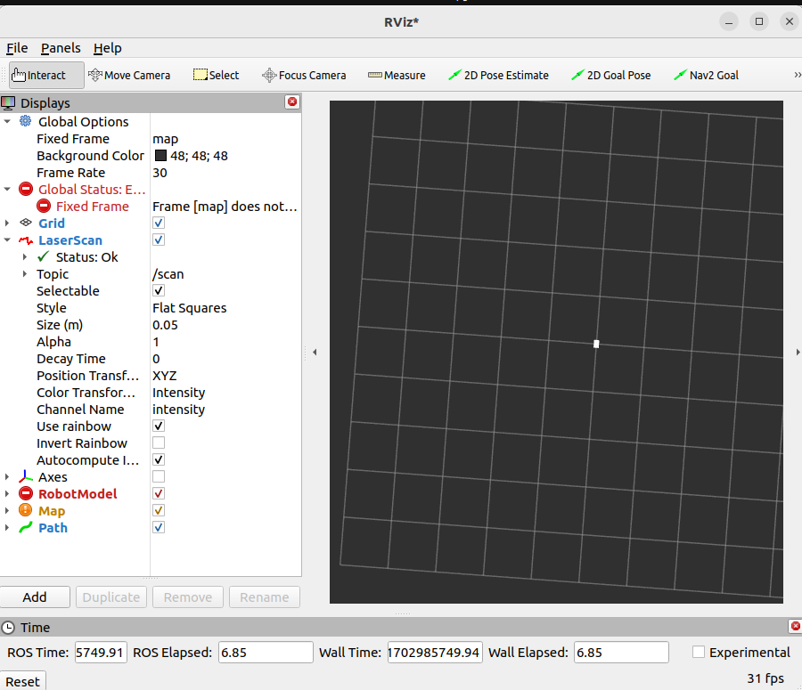
Change [Fixed Frame] to base_linke to display the car model.
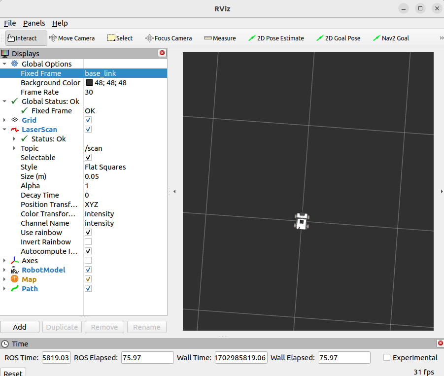
Then, use the mouse to adjust the viewing angle, slide the simulation controller just generated, and you can see that the tires/camera of the car are changing.
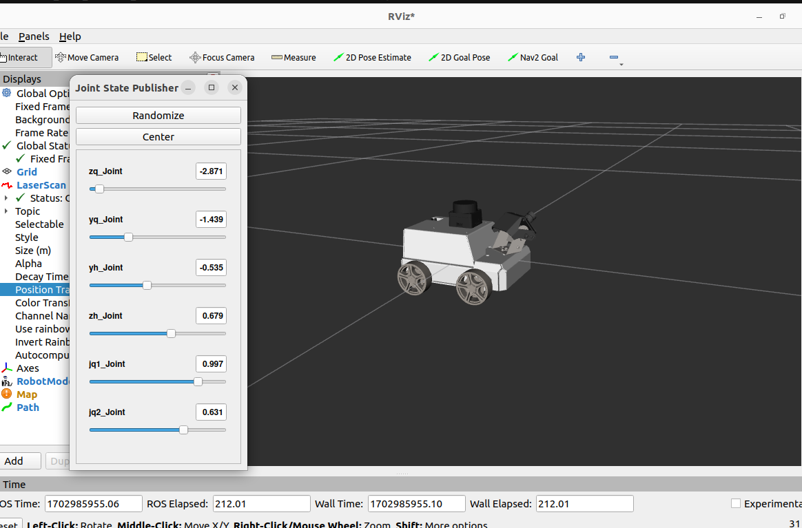
zq_Joint:Control left front wheel
yq_Joint:Control right front wheel
yh_Joint:Control right rear wheel
zh_Joint:Control left rear wheel
jq1_Joint:Control PTZ 1
jq2_Joint:Control PTZ 2
Randomize:Randomly publish values to each joint
Center:All Joints are centered
3、Code analysis
Code location (take virtual machine as an example)
xxxxxxxxxx/home/yahboom/yahboomcar_ws/src/yahboomcar_description/launchdisplay_launch.py
xfrom ament_index_python.packages import get_package_share_path
from launch import LaunchDescriptionfrom launch.actions import DeclareLaunchArgumentfrom launch.substitutions import Command, LaunchConfiguration
from launch_ros.actions import Nodefrom launch_ros.parameter_descriptions import ParameterValue
def generate_launch_description(): urdf_tutorial_path = get_package_share_path('yahboomcar_description') default_model_path = urdf_tutorial_path / 'urdf/MicroROS.urdf'
model_arg = DeclareLaunchArgument(name='model', default_value=str(default_model_path), description='Absolute path to robot urdf file') robot_description = ParameterValue(Command(['xacro ', LaunchConfiguration('model')]), value_type=str)
robot_state_publisher_node = Node( package='robot_state_publisher', executable='robot_state_publisher', parameters=[{'robot_description': robot_description}] )
joint_state_publisher_gui_node = Node( package='joint_state_publisher_gui', executable='joint_state_publisher_gui' )
tf_base_footprint_to_base_link = Node( package='tf2_ros', executable='static_transform_publisher', arguments=['0', '0', '0.05', '0.0', '0.0', '0.0', 'base_footprint', 'base_link'], ) return LaunchDescription([ model_arg, joint_state_publisher_gui_node, robot_state_publisher_node, tf_base_footprint_to_base_link ])model_arg:Load model parameters. The loaded model is MicroROS.urdf, located at
/home/yahboom/yahboomcar_ws/src/yahboomcar_description/urdfjoint_state_publisher_gui_node:Publish sensor_msgs/JointState message
robot_state_publisher_node:Robot status release
tf_base_footprint_to_base_link:Publish a static transformation of base_footprint to base_link
4、URDF model
URDF, the full name of Unified Robot Description Format, translated into Chinese as Unified Robot Description Format, is a robot model file described in xml format, similar to D-H parameters.
xxxxxxxxxx<?xml version="1.0" encoding="utf-8"?>
The first line is a required item for XML and describes the version information of XML.
xxxxxxxxxx<robot name="name="micro4.0"></robot>The second line describes the current robot name; all information about the current robot is contained in the [robot] tag.
4.1、component
link,The connecting rod can be imagined as a human arm
joint,The joint can be imagined as a human elbow joint
The relationship between link and joint: Two links are connected through joints. Imagine that an arm has a forearm (link) and an upper arm (link) connected through an elbow joint (joint).
4.1.1、link
1)、Introduction
In the URDF descriptive language, link is used to describe physical properties.
Describe the visual display, labels.
Describe collision properties, tags.
Describes physical inertia, the label is not commonly used.
Links can also describe the size, color, shape, inertial matrix, collision properties, etc. Each Link will become a coordinate system.
2)、Sample code
xxxxxxxxxx<link name="base_link"> <inertial> <origin xyz="-0.0038187037800903 -0.000532399212617988 -0.00668209865413972" rpy="0 0 0" /> <mass value="0.222555109690442" /> <inertia ixx="0.000160582675692647" ixy="-8.18530574494391E-07" ixz="-2.74575507729664E-06" iyy="0.000176217109527607" iyz="1.64721285063183E-07" izz="0.000302441932451338" /> </inertial> <visual> <origin xyz="0 0 0" rpy="0 0 0" /> <geometry> <mesh filename="package://yahboomcar_description/meshes/base_link.STL" /> </geometry> <material name=""> <color rgba="1 1 1 1" /> </material> </visual> <collision> <origin xyz="0 0 0" rpy="0 0 0" /> <geometry> <mesh filename="package://yahboomcar_description/meshes/base_link.STL" /> </geometry> </collision> </link>3)、Tag
introduction
origin:It describes the pose information; the xyz attribute describes the coordinate position in the general environment, and the rpy attribute describes its own posture.
mess:Describes the quality of the link.
inertia:The inertial reference system, due to the symmetry of the rotational inertia matrix, only requires 6 upper triangular elements ixx, ixy, ixz, iyy, iyz, izz as attributes.
geometry:The label describes the shape; the main function of the mesh attribute is to load the texture file, and the filename attribute is the file address of the texture path.
material:The label describes the material; the name attribute is required, can be empty, and can be repeated. Through rgba in the [color] tag
4.1.2、joints
1)、Introduction
Describe the relationship between two joints, motion position and speed limits, kinematic and dynamic properties. The types of joints are as follows:
fixed:Immobilize joints. No movement is allowed and it serves as a connection.
continuous:Rotating joints. Can continue to rotate, there is no limit on the rotation angle.
revolute:Rotating joints. Similar to continuous, there is a limit on the rotation angle.
prismatic:Sliding joints. Move along a certain axis, with position restrictions.
floating:Suspended joints. It has six degrees of freedom, 3T3R.
planar:Planar joints. Allows translation or rotation orthogonally to the plane.
2)、Sample code
xxxxxxxxxx<joint name="zq_Joint" type="continuous"> <origin xyz="0.0455 0.0675 -0.02125" rpy="0 0 0" /> <parent link="base_link" /> <child link="zq_Link" /> <axis xyz="0 1 0" /></joint>In the [joint] tag, the name attribute is required, which describes the name of the joint and is unique. In the type attribute of the [joint] tag, fill in the six joint types correspondingly.
3)、Tag introduction
origin:The child label refers to the relative position of the rotating joint to the coordinate system where the parent is located.
parent,child:parent,The child tag represents two links to be connected; the parent is the reference object, and the child rotates around the praent.
axis:The child tag indicates which axis (xyz) the link corresponding to the child rotates around and the amount of rotation around the fixed axis.
limit:Subtags are mainly used to restrict child.。The lower attribute and upper attribute limit the arc range of rotation, and the effort attribute limits the force range during rotation.(Positive and negative value, unit is N ),The speed attribute limits the rotation speed in m/s.
mimic:Describe the relationship of this joint to existing joints.
safety_controller:Describes safety controller parameters. Protect the movement of robot joints.