Welcome to MicroROS Robot Expansion Board repository
Angular velocity calibration
Angular velocity calibration
Note: The virtual machine needs to be in the same LAN as the car, and the ROS_DOMAIN_ID needs to be consistent. You can check [Must read before use] to set the IP and ROS_DOMAIN_ID on the board.
1、Program function description
The car connects to the agent, runs the program, and adjusts the parameters here through the dynamic parameter adjuster to calibrate the car's angular velocity. The intuitive reflection of the calibrated angular speed is to give the car a command to rotate 360 degrees (one revolution) to see how many degrees it actually rotates and whether it is within the error range.
2、Start and connect to the agent
Taking the supporting virtual machine as an example, enter the following command to start the agent:
sudo docker run -it --rm -v /dev:/dev -v /dev/shm:/dev/shm --privileged --net=host microros/micro-ros-agent:humble udp4 --port 8090 -v4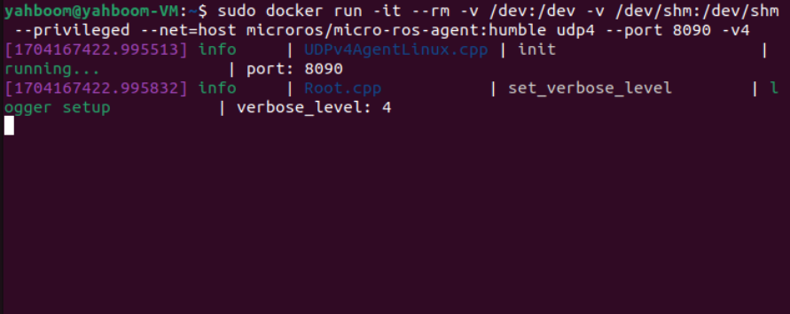
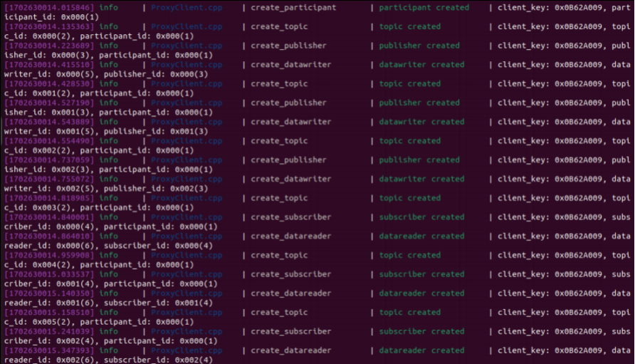
Then, turn on the car switch and wait for the car to connect to the agent. The connection is successful, as shown in the figure below.
3、starting program
First, start the car's underlying data processing program. This program will release the TF transformation of odom->base_footprint. With this TF change, you can calculate "how many degrees the car has turned" and and enter the following command in the terminal
xxxxxxxxxxros2 launch yahboomcar_bringup yahboomcar_bringup_launch.py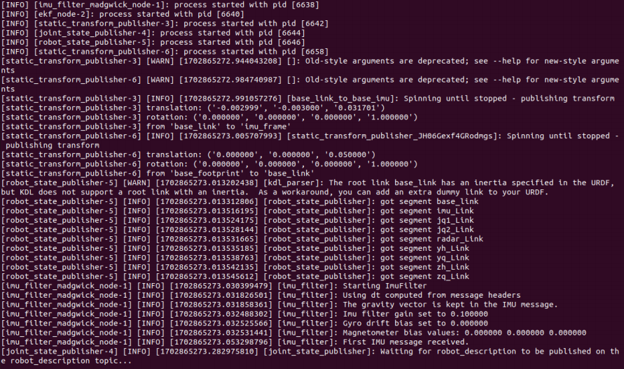
Then, start the car angular velocity calibration program and enter the following command in the terminal
xxxxxxxxxxros2 run yahboomcar_bringup calibrate_angular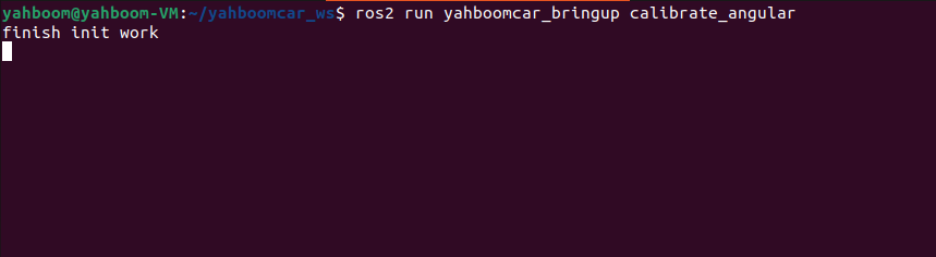
Finally, open the dynamic parameter adjuster and enter the following command in the terminal,
xxxxxxxxxxros2 run rqt_reconfigure rqt_reconfigure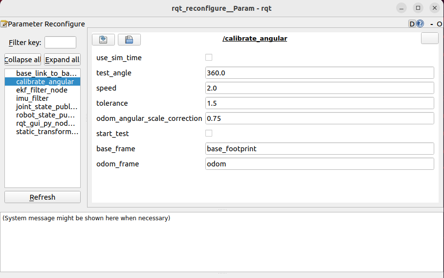
Note: There may not be the above nodes when you first open it. You can see all nodes after clicking Refresh. The calibrate_angular node shown is the node for calibrating angular velocity.
4、Start calibration
In the rqt_reconfigure interface, select the calibrate_angular node. There is start_test below. Click the box to the right of it to start calibration. Other parameters in the rqt interface are described as follows.
test_angle:Calibrate the test angle, here the test rotates 360 degrees
speed:Angular velocity magnitude;
tolerance:tolerance for error;
odom_angular_scale_correction:Linear speed proportional coefficient, if the test result is not ideal, just modify this value;
start_test:test switch;
base_frame:The name of the base coordinate system;
odom_frame:The name of the odometer coordinate system.
Click start_test to start calibration. The car will monitor the TF transformation of base_footprint and odom, calculate the theoretical distance traveled by the car, wait until the error is less than the tolerance, and issue a parking instruction.
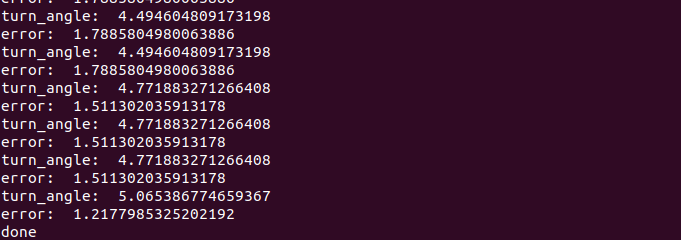
The turn_angle here is in radians. If the actual angle of the car's rotation is not 360 degrees, then modify the odom_angular_scale_correction parameter in rqt. After modification, click on the blank space, click start_test again, reset start_test, and then click start_test again. Calibration. The same goes for modifying other parameters. You need to click on the blank space to write the modified parameters.
5、Code analysis
Source code reference path (taking the supporting virtual machine as an example):
xxxxxxxxxx/home/yahboom/yahboomcar_ws/src/yahboomcar_bringup/yahboomcar_bringupcalibrate_angular.py, the core code is as follows,
x
#Monitor the TF transformation of base_footprint and odomdef get_odom_angle(self): try: now = rclpy.time.Time() rot = self.tf_buffer.lookup_transform(self.odom_frame,self.base_frame,now) #print("oring_rot: ",rot.transform.rotation) cacl_rot = PyKDL.Rotation.Quaternion(rot.transform.rotation.x, rot.transform.rotation.y, rot.transform.rotation.z, rot.transform.rotation.w) #print("cacl_rot: ",cacl_rot) angle_rot = cacl_rot.GetRPY()[2] #print("angle_rot: ",angle_rot) return angle_rot
except (LookupException, ConnectivityException, ExtrapolationException): self.get_logger().info('transform not ready') raise return#Calculate the angle and error of rotationself.odom_angle = self.get_odom_angle() self.delta_angle = self.odom_angular_scale_correction * self.normalize_angle(self.odom_angle - self.first_angle)#print("delta_angle: ",self.delta_angle)self.turn_angle += self.delta_angleprint("turn_angle: ",self.turn_angle)self.error = self.test_angle - self.turn_angle