yahboom
HomeLearn
Solution
Blog
Online Store
About Us
EN/中文
MicroROS Robot Expansion Board📖
01. microROS control board development environment
  • 1. Introduction to microROS control board
  • 2. Set up ESP32-IDF development environment
  • 3. ESP32-IDF configuration tool
  • 4. Install ESP32-microros components
  • 5. Install and start microROS agent
  • 6. Flash-tool burning firmware
02. ESP32 basic course
  • 1. Turn on the LED light
  • 2. Button function
  • 3. Drive the buzzer
  • 4. Serial communication
  • 5. Battery voltage detection
  • 6. Drive PWM servo
  • 7. Drive motor
  • 8. Read motor encoder data
  • 9. PID controls car speed
  • 10. Read IMU data
  • 11. Read radar data
  • 12. Flash access data
  • 13. Partition table and memory
  • 14. Bluetooth communication
  • 15. WiFi networking
  • 16. Robot kinematics analysis
  • 17.Drive ESP32 WiFi camera
03. microros basic course
  • 1.Publish topic
  • 2. Subscribe topic
  • 3. Multi-topic subscribe and publish
  • 4. Subscribe buzzer topics
  • 5. Subscribe PWM servo topics
  • 6. Subscribe speed control topics
  • 7. Release speed topic
  • 8. Release IMU data topic
  • 9. Publish lidar data topics
  • 10. Customized transmission method
04.ROS2 basic course
  • 1. Introduction to ROS2
  • 2.ROS2 install Humble
  • 3.ROS2 development environment
  • 4.ROS2 workspace
  • 5.ROS2 function package
  • 6.ROS2 node
  • 7.ROS2 topic communication
  • 8.ROS2 service communication
  • 9.ROS2 action communication
  • 10.ROS2 custom interface message
  • 11.ROS2 parameter service case
  • 12.ROS2 meta-function package
  • 13.ROS2 distributed communication
  • 14.ROS2 DDS
  • 15.ROS2 time related API
  • 16.ROS2 common command tools
  • 17.ROS2 rviz2 use
  • 18.ROS2 rqt toolbox
  • 19.ROS2 Launch startup file configuration
  • 20.ROS2 recording and playback tool
  • 21.ROS2 URDF model
  • 22.ROS2 Gazebo simulation platform
  • 23.ROS2 TF2 coordinate transformation
05. Robot basic course
4.1 Robot information release
  • Robot information release
4.0 Preparation
  • 1. Write firmware
  • 2. How to install and use VM
  • 3. microROS control board configuration
  • 4. Connect to microROS agent
4.2 Robot keyboard control
  • Robot keyboard control
4.3 Robot handle control
  • Robot handle control
4.4 Robot state estimation
  • Robot state estimation
4.5 Line speed calibration
  • Line speed calibration
4.6 Angular velocity calibration
  • Angular velocity calibration
4.7 Robot URDF model
  • Robot URDF model
Download
  • Firmware And Code
  • VM_File
  • 3D Model File
  • ROS2_Basic_VM
Download ZIP

Welcome to MicroROS Robot Expansion Board repository

3. microROS control board configuration

microROS control board configuration


  1. The Micro ROS control board has been programmed with factory firmware before leaving the factory. If the firmware of other routines has been burned, please re-burn the factory firmware before supplying power to the board and turning on the power switch.

  2. Copy the configuration script (config_robot.py) file included in the product information to the virtual machine/computer.

  3. If the virtual machine/computer has an external USB serial port device, please temporarily remove the USB external serial port device from the virtual machine/computer, and then use a type-C data cable to connect the serial port of the virtual machine/computer and the microROS control board. At this time, the system pops up a window, please choose to connect to the virtual machine.

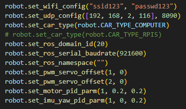
  4. Edit the config_robot.py file, drag it to the bottom of the file, update the parameters of the set_wifi_config function according to your own WiFi network name and password, and update the parameters of the set_udp_config function according to the IP address of the virtual machine/computer. The virtual machine/computer version needs to set the robot type. is CAR_TYPE_COMPUTER. Keep other parameters as default or modify them as needed. Save the configuration file.
img

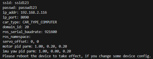
  1. First, briefly press the reset button on the microROS control board. It will be in the configuration state within 5 seconds of booting (the MCU indicator light flashes once every 300 milliseconds). Then run the following command to configure the robot. At this time, check whether the returned data is consistent with your own settings. If it is consistent, the setting is successful.

python3 config_robot.py
img

  1. Press the reset button of the robot to reload the configuration. At this point, the type-C data cable connecting the robot to the virtual machine/computer can be removed.

How to install and use VM
Connect to microROS agent

COMPANY

  • About us
  • Team Style
  • Blog

LEARNING & EXPLORATION

  • Tutorials
  • Edge AI hardware
  • Educational robots
  • Embedded intelligent hardware

WHERE TO BUY

  • Yahboom Online Store
  • Amazon
  • Alibaba
  • AliExpress
  • Mercado

TECHNOLOGY SUPPORT

  • Email: support@yahboom.com

BE A DISTRIBUTOR

  • Email: sales@yahboom.com
QR Code
QR Code

Copyright © 2017-2026 Yahboom. All Rights Reserved.

EN/中文