Welcome to RDK S600 Developer Kit repository
1.6 MCU Interface Expansion Board
MCU Interface Expansion Board
Product Documentation URL:https://developer.d-robotics.cc/rdk_s_doc/en/Quick_start/hardware_introduction/rdk_s600/rdk_s600_mcu_port_expansion_board?v=5.1.0&p=RDK+S600
1.Product Introduction
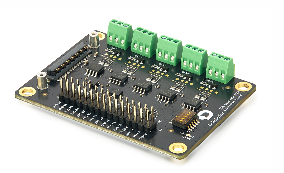
The RDK S600 MCU Port Expansion Board (including the matching FPC) is a core expansion module for the D-Robotics RDK S600 series developer kit. It is mainly used to expand MCU interface functions, supporting CAN_FD, ADC, etc.
warning
- This product is only compatible with the RDK S600 series mainboard. Do not use it with other device models.
- During use, place the expansion board on a stable, flat, and non-conductive surface to avoid the device falling or short-circuiting due to unstable support.
- If an incompatible device is connected to this MCU expansion board, this product does not provide repair services for any resulting device damage.
- All peripheral devices used with this product (including but not limited to CAN devices) must comply with the safety and performance standards of the country/region of use and bear appropriate compliance certification marks.
- All cables and connectors of peripheral devices connected to this expansion board must have sufficient insulation performance to meet electrical safety requirements.
Safe Usage
To avoid malfunction or damage to this expansion board, strictly follow these guidelines:
- Environmental Requirements: Do not expose to water, moisture, or conductive surfaces during operation. Keep away from heat sources (e.g., heaters, direct sunlight). Ensure the operating environment temperature complies with the product specification requirements.
- Assembly Operations: Handle with care during assembly. Avoid applying mechanical pressure or electrical interference (such as electrostatic discharge) to the printed circuit board (PCB) and connectors.
- Power-On Operations: Do not touch the PCB surface or metal interfaces on the edge of the device while powered on to reduce the risk of electrostatic discharge (ESD) damage.
2.Product Specifications
| Item | Parameters |
|---|---|
| Interfaces | 5 x CAN FD (up to 8Mbps) 1 x 30-pin, supporting up to 7x ADC, 2x IIC, 2x SPI |
| Onboard Module | IMU:BMI088(SPI) |
| Operating Temp | 0℃~65℃ |
| Dimensions | 70x70x17mm |
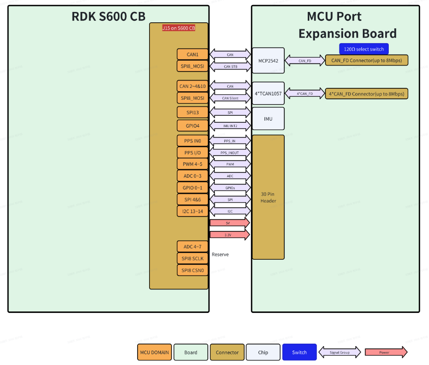
Architecture Diagram
Interface Description
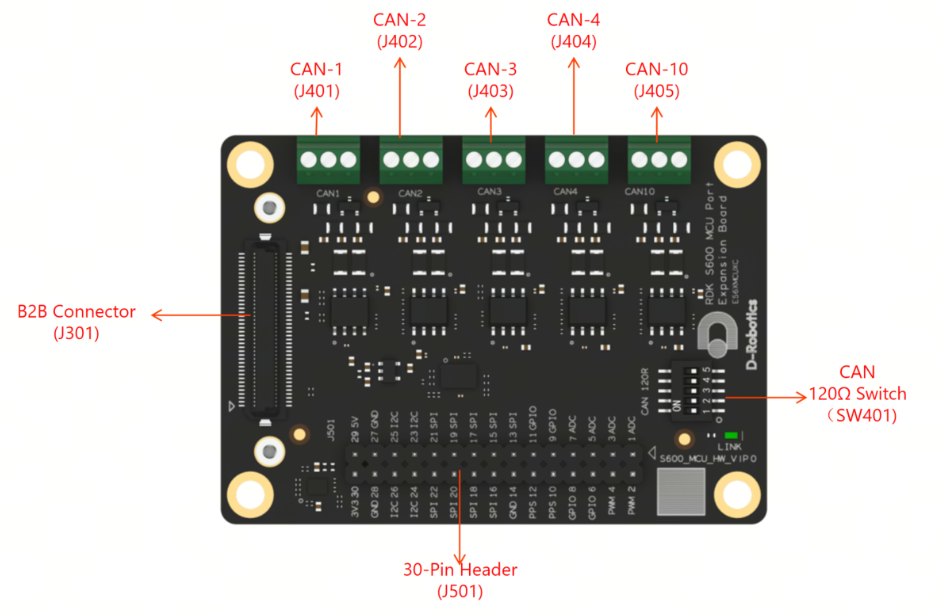
| Reference | Function |
|---|---|
| J301 | MCU Expansion Board 80-pin Connector |
| J401 | MCU-CAN1 Interface |
| J402 | MCU-CAN2 Interface |
| J403 | MCU-CAN3 Interface |
| J404 | MCU-CAN4 Interface |
| J405 | MCU-CAN10 Interface |
| J501 | 30-Pin Interface |
| SW401 | MCU CAN 120Ω Switch |
Assembly Instructions
Important Reminders
- Perform the installation only when the development board is powered off and the DC plug is disconnected.
- Keep the connectors aligned parallel during assembly. Mate the connectors evenly with consistent force and ensure a secure connection to prevent damage.
Tips
The side of the FPC cable marked with "CB" on the silkscreen corresponds to the J15 connector on the RDK S600 mainboard. The side marked with "SUB" corresponds to the J301 connector on this expansion board.
3.Interface Details
CAN FD Connectors (J401/J402/J403/J404/J405)
The back of the expansion board indicates CAN_H, CAN_L, and GND for each interface.D
The expansion board provides 5 CAN FD interfaces (CAN-1~CAN-4, CAN-10). Each interface is equipped with a 120Ω terminal resistor, which can be toggled via the switch (SW401).
30-Pin(J501)
Pin definition: drobotics_rdk_s600_mcu_port_expansion_board_pinlist_v1p0.xlsx
When using the following 5 IOs from the 30-Pin Connector with peripherals, ensure that the default power-on high/low state of the corresponding peripheral pins matches the Pull Up/Down state specified in the Pin Definition file. Do not add or connect additional pull-up/pull-down resistors:
- PIN11: MCU_GPIO0_3V3
- PIN15: MCU_SPI4_CSN0_3V3
- PIN19: MCU_SPI4_MOSI_3V3
- PIN16: MCU_SPI6_CSN0_3V3
- PIN20: MCU_SPI6_MOSI_3V3
- PIN13: MCU_SPI4_CSN1_3V3
IMU(U301)
Integrated Inertial Measurement Unit (IMU, model Bosch Sensortec BMI088), supporting communication control via the SPI-13 serial bus.
4.Indicator Light
Below the 5 switches (SW401) on the expansion board, there is one green LED indicator (labeled "LINK") used to indicate the power status and the connection status between the MCU expansion board and the RDK S600:
- Green light constantly on: The RDK S600 and MCU expansion board are connected normally, and 5V power is being supplied correctly.
- Green light off: The connection between the RDK S600 and MCU expansion board is abnormal, with no 5V power supply.