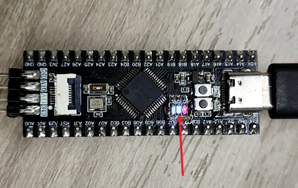
Welcome to MSPM0G3519 Development Board repository
1. Turn on the LED light
Turn On LED Light
Turn On LED Light1. Learning Objectives2. Hardware Setup3. Experiment Steps1. Open SYSCONFIG Configuration Tool2. Parameter Settings2.1 Set Port Parameters2.2 Set Pin Parameters2.3 Save and Update Configuration File3. Write Program4. Compile4. Program Analysis5. Experimental Phenomena
1. Learning Objectives
Learn the basic use of MSPM0G3519 motherboard pins.
Understand how to control the onboard LED light.
2. Hardware Setup
This course does not require additional hardware. You can directly use the onboard LED light on the MSPM0G3519 motherboard.
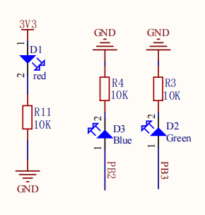
We have set up two LED user lights on the motherboard. Users can customize their functions. The following uses LED1 as an example.
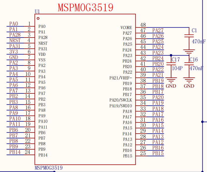
MSPM0G3519 Main Control Diagram
LED Part Schematic
3. Experiment Steps
1. Open SYSCONFIG Configuration Tool
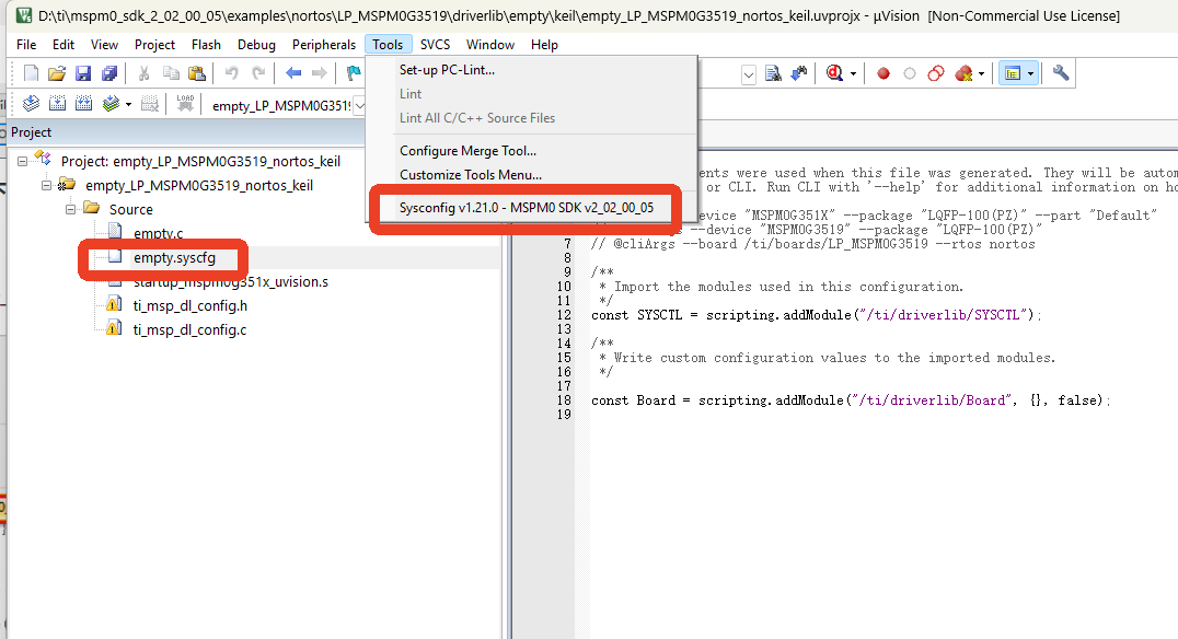
Open the empty project from the SDK in KEIL.
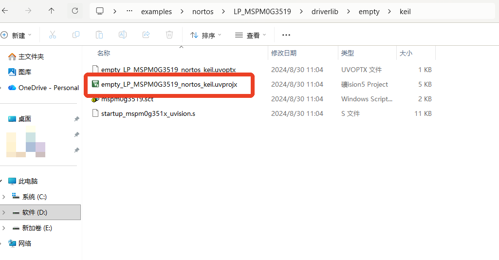
After selecting and opening it, open the empty.syscfg file in the KEIL interface. With the empty.syscfg file open, then open the SYSCONFIG GUI interface from the Tools menu.
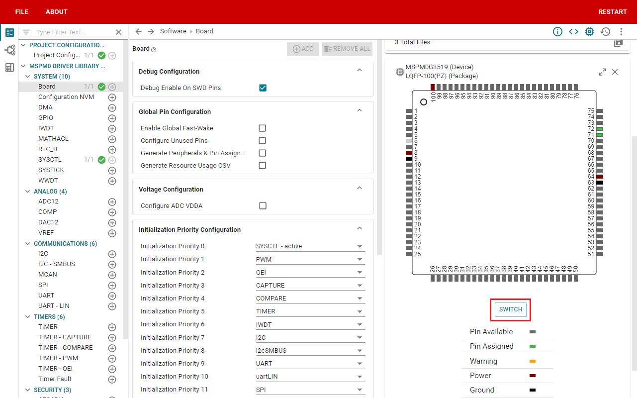
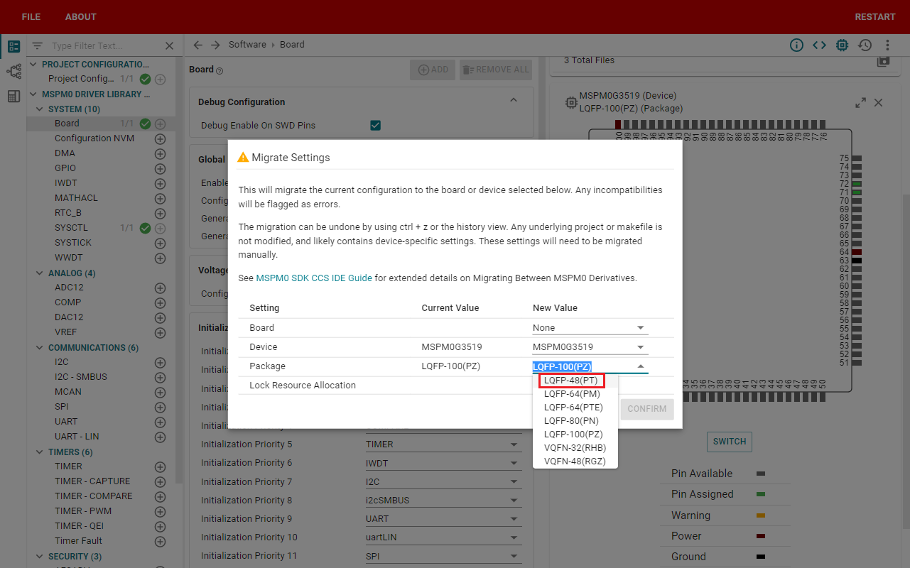
In SYSCONFIG, Modify chip pin package
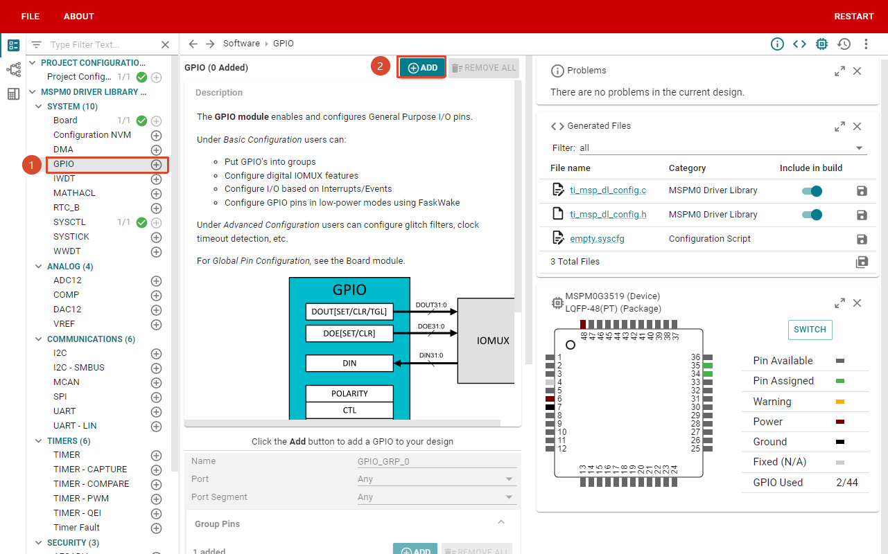
select MCU peripherals on the left, find the GPIO option and click to enter. Click ADD in GPIO to add a GPIO group.
2. Parameter Settings
2.1 Set Port Parameters
Configure GPIO parameters and name the pin LED1.
From the LED part schematic, LED1 is on port PB2, so set Port to PORTB.
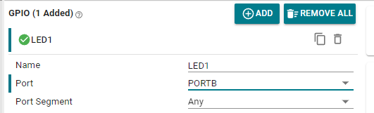
Parameter description:
Name: Custom name for the GPIO instance. By default, the name starts with the numeric suffix "0". You can customize the name to reflect the module's purpose (for example, naming the GPIO "LED1" so you know this pin is specifically for controlling LED1).
Port: The GPIO instance's port. LED is connected to GPIOB2 pin, so only PORTB can be selected.
Port Segment: Set port pull-up/down resistor. Note this is port pull-up/down, which sets the entire GPIOB port.
2.2 Set Pin Parameters
Set the pin to output mode, set the pin to output low level by default, set the pin to pull-down mode, set the pin to GPIOB_2, do not enable interrupt events.
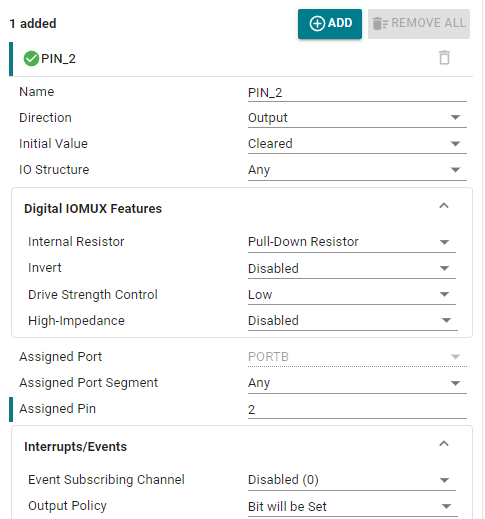
Parameter description:
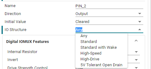
Name: User-defined pin name, set to PIN_2.
Direction: Set pin mode, input and output. Here we are controlling the LED light, so select output mode.
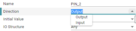
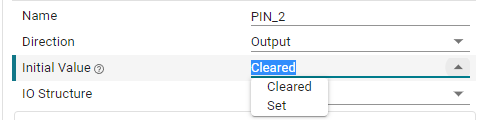
Initial Value: Set the initial state of the pin, can only be set when configured as output mode. There are two options, clear and set. Clear means output low level, set means output high level.
IO Structure: Set IO structure. There are multiple options: Default (Any), Standard, Wake (Standard with Wake), High-Speed, and 5V Tolerant Open Drain.
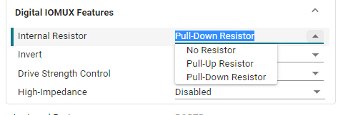
Internal Resistor: Set pin pull-up/down resistor. There are three options: none, pull-up, and pull-down resistor. Based on the LED connection method, pull-down resistor is selected here.
Assigned Pin: Set pin number. Enter the corresponding pin number for whichever pin you want to control. For example, the LED on the development board is connected to GPIOB2, so enter 2.
2.3 Save and Update Configuration File
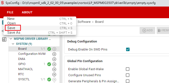
Click SAVE to save the SYSCONFIG configuration, then close SYSCONFIG and return to KEIL.
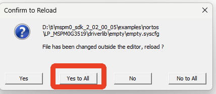
Select Yes to All in the popup.
Now you can see that the empty.syscfg file has been updated with our set parameters.
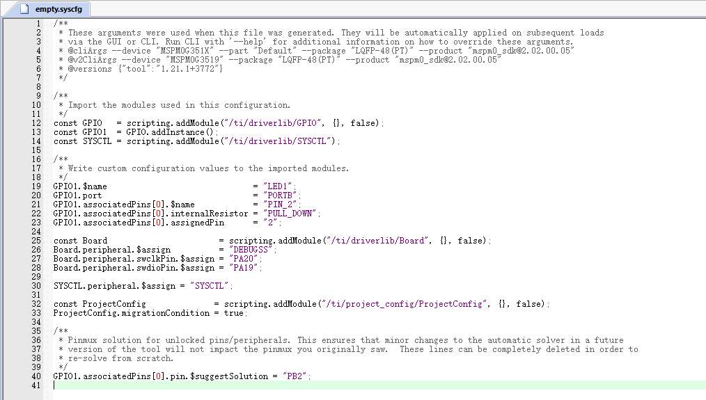
We also need to confirm whether the .c and .h files are updated. Simply compile, and the compilation will automatically update to KEIL. If not updated, we can also copy the file content from SYSCONFIG.
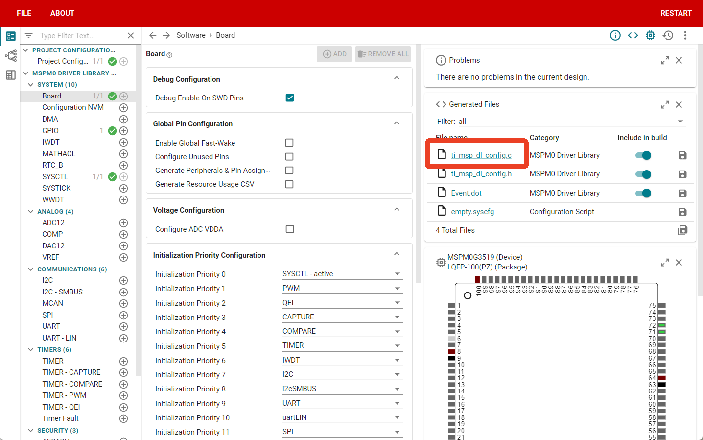
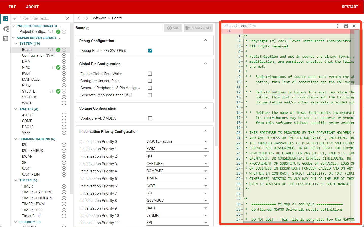
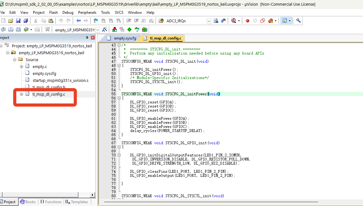
The .h file is the same. You can copy the content from SYSCONFIG.
3. Write Program
In the empty.c file, write the following code
x#include "ti_msp_dl_config.h"
//Custom delay (not precise)void delay_ms(unsigned int ms){ unsigned int i, j; // The number of nested loops below is roughly calculated based on the master control frequency and the instruction cycle generated by the compiler, and needs to be adjusted through actual testing to achieve the required delay. for (i = 0; i < ms; i++) { for (j = 0; j < 8000; j++) { // Perform only one operation that is simple enough to predict its execution time __asm__("nop"); // "nop" stands for "no operation", which on most architectures consumes one or a few clock cycles } }}
int main(void){ SYSCFG_DL_init(); while (1) { DL_GPIO_clearPins(LED1_PORT,LED1_PIN_2_PIN);//Output low level delay_ms(1000);//Delay about 1S DL_GPIO_setPins(LED1_PORT,LED1_PIN_2_PIN); //Output high level delay_ms(1000);//Delay about 1S }}4. Compile
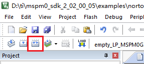
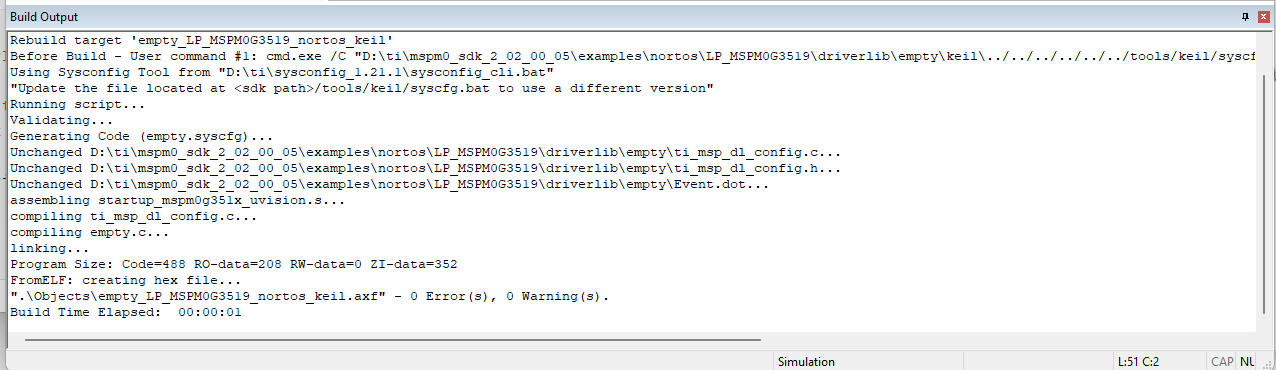
Click the Rebuild icon. The following prompt indicates compilation is complete with no errors.
4. Program Analysis
dl_gpio.h
xxxxxxxxxx/** *  @brief      Set a group of GPIO pins * *  @param[in]  gpio  Pointer to the register overlay for the peripheral *  @param[in]  pins  Pins to set high. Bitwise OR of @ref DL_GPIO_PIN. */__STATIC_INLINE void DL_GPIO_setPins(GPIO_Regs* gpio, uint32_t pins){    gpio->DOUTSET31_0 = pins;}
/** *  @brief      Clear a group of GPIO pins * *  @param[in]  gpio  Pointer to the register overlay for the peripheral *  @param[in]  pins  Pins to clear. Bitwise OR of @ref DL_GPIO_PIN. */__STATIC_INLINE void DL_GPIO_clearPins(GPIO_Regs* gpio, uint32_t pins){    gpio->DOUTCLR31_0 = pins;}
/** *  @brief      Toggle a group of GPIO pins * *  @param[in]  gpio  Pointer to the register overlay for the peripheral *  @param[in]  pins  Pins to toggle. Bitwise OR of @ref DL_GPIO_PIN. */__STATIC_INLINE void DL_GPIO_togglePins(GPIO_Regs* gpio, uint32_t pins){    gpio->DOUTTGL31_0 = pins;}
__STATIC_INLINE void DL_GPIO_setPins(GPIO_Regs* gpio, uint32_t pins): This function controls pins to output high level.
__STATIC_INLINE void DL_GPIO_clearPins(GPIO_Regs* gpio, uint32_t pins): This function controls pins to output low level.
__STATIC_INLINE void DL_GPIO_togglePins(GPIO_Regs* gpio, uint32_t pins): This function toggles pin level. If it was high level, it becomes low level. If it was low level, it becomes high level.
empty.c
xxxxxxxxxxint main(void){ SYSCFG_DL_init(); while (1) { DL_GPIO_clearPins(LED1_PORT,LED1_PIN_2_PIN);//Output low level delay_ms(1000);//Delay about 1S DL_GPIO_setPins(LED1_PORT,LED1_PIN_2_PIN); //Output high level delay_ms(1000);//Delay about 1S }}Set PB2 to output low level, delay about 1s, then output high level, then delay about 1s. Repeat this process.
5. Experimental Phenomena
After the program is downloaded, you can see LED1 on the MSPM0 development board light up and blink approximately every 1 second.