Welcome to MSPM0G3519 Development Board repository
5. Serial Communication
Serial Communication
Serial Communication1. Learning ObjectivesSerial CommunicationSerial Working Modes2. Hardware Setup3. Experiment Steps1. Open SYSCONFIG Configuration Tool2. Serial Clock Configuration3. Serial Parameter Configuration4. Write Program5. Compile4. Program Analysis5. Experimental Phenomena
1. Learning Objectives
Learn the basic use of serial communication on the MSPM0G3519 motherboard.
Understand basic serial communication knowledge.
Serial Communication
Serial Communication refers to the communication method between peripherals and computers through data signal lines and ground lines, transmitting data bit by bit. It belongs to serial communication.
Key parameters for serial communication include baud rate, data bits, stop bits, and parity bits. To ensure normal communication, these parameters must be consistent between both communicating parties.
Serial Working Modes
Simplex Mode
Characteristics: Data can only be transmitted in one direction. The sender is responsible for sending, and the receiver is responsible for receiving. There is no reverse communication.
Applications: Suitable for scenarios where only one-way information transmission is needed, such as sensor data output.
Full-Duplex Mode
Characteristics: Data can be transmitted simultaneously in both directions. Sending and receiving do not interfere with each other.
Implementation: Requires two data lines, one for sending (TX) and one for receiving (RX).
Applications: Often used in scenarios requiring efficient, real-time communication, such as computer and peripheral interaction.
Half-Duplex Mode
Characteristics: Data can be transmitted in both directions but cannot be simultaneous. Sending and receiving must alternate.
Implementation: Sending and receiving share one communication line, relying on timing to switch directions.
Applications: Suitable for scenarios with low real-time requirements, such as walkie-talkie communication.
These three modes adapt to different communication needs and can be flexibly chosen based on specific application scenarios.
2. Hardware Setup
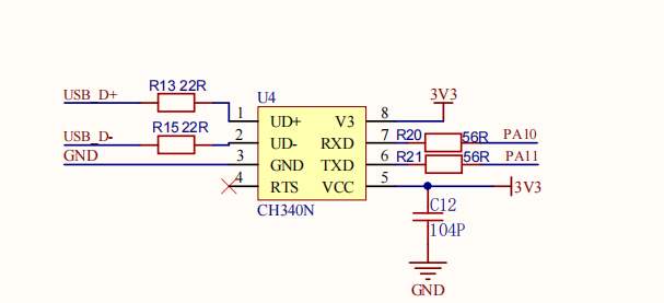
Since the development board has a built-in CH340 serial circuit, you can directly use a USB cable for serial communication without an external USB-to-TTL module.
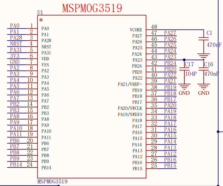
MSPM0G3519 Main Control Diagram
Type-C Part Schematic
3. Experiment Steps
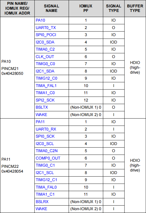
This course uses the UART0 peripheral on pins PA10 and PA10, combined with the CH340 USB-to-serial chip on the development board, to receive serial data sent from the upper computer and then send the data back to the upper computer through the serial send function.
1. Open SYSCONFIG Configuration Tool
Open the empty project from the SDK in KEIL.
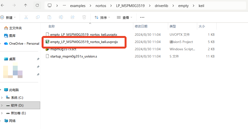
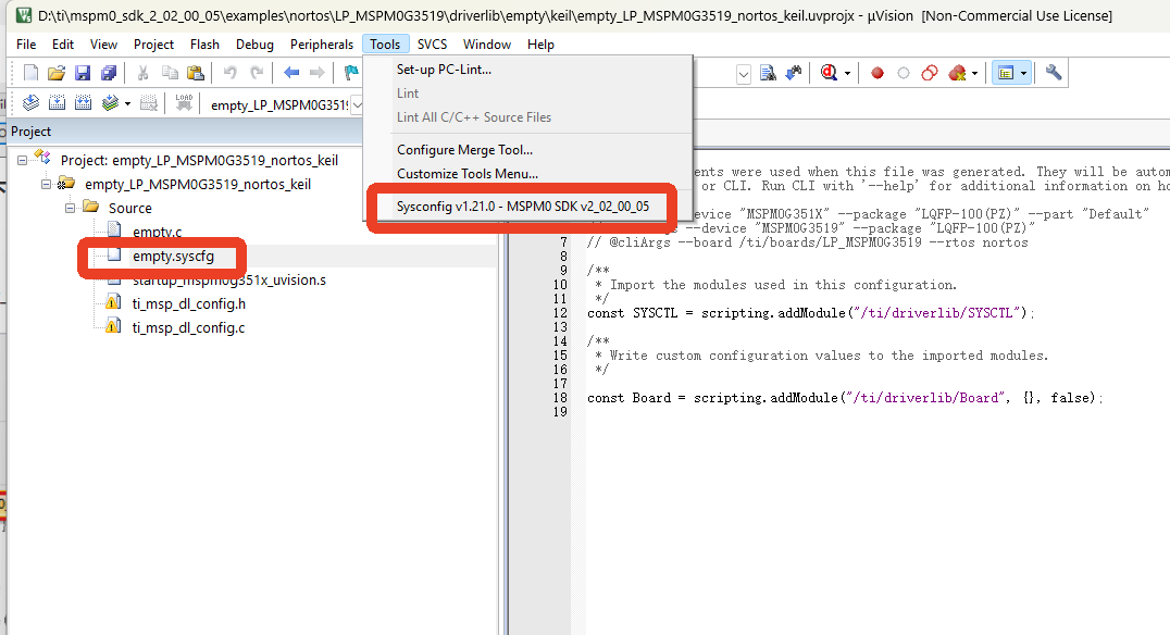
After selecting and opening it, open the empty.syscfg file in the KEIL interface. With the empty.syscfg file open, then open the SYSCONFIG GUI interface from the Tools menu.
2. Serial Clock Configuration
The serial clock source has three options:
BUSCLK: CPU clock provided by the internal high-frequency oscillator, usually set to 32MHz at chip factory settings.
MFCLK: Can only use a fixed 4MHz clock. To enable it, you need to configure the SYSOSC_4M branch in the clock tree to enable it properly.
LFCLK: Clock provided by the internal low-frequency oscillator (32KHz). Effective in run, sleep, stop, and standby modes. Using this clock can achieve lower power consumption.
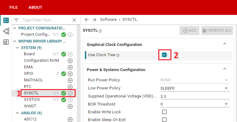
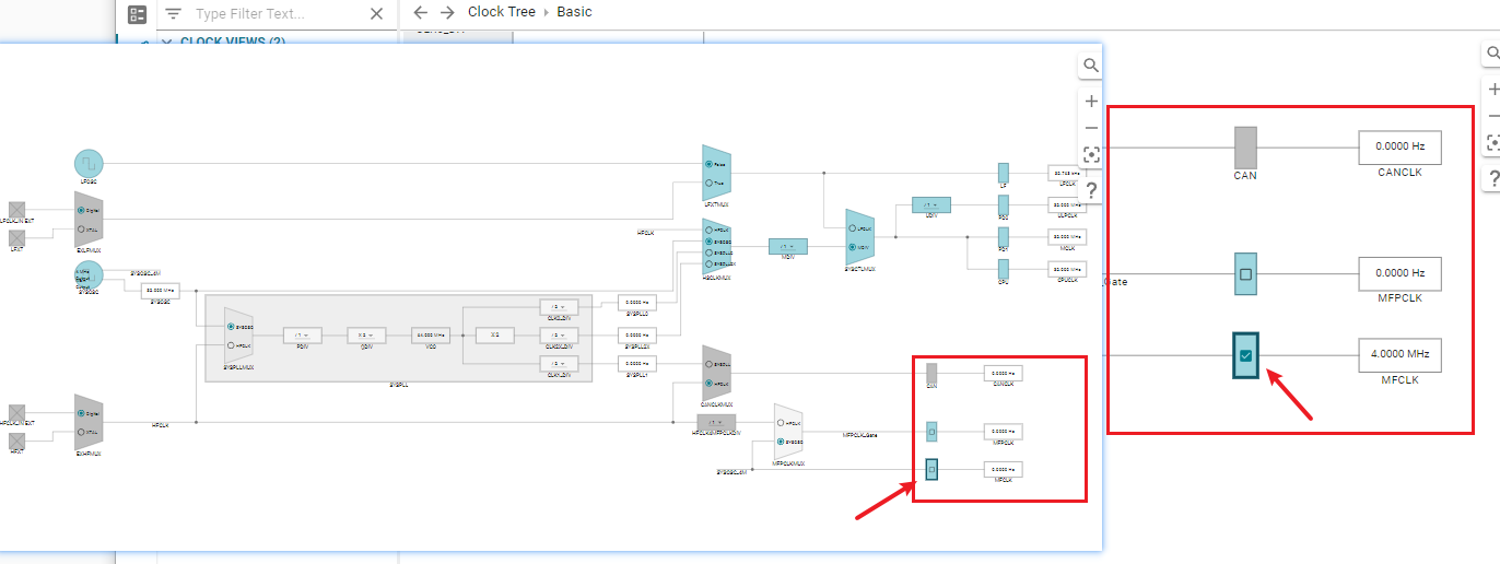
This case uses MFCLK as the serial clock source. To enable MFCLK, you need to configure the clock tree in SYSCONFIG. Find the SYSCTL option in the left tab of SYSCONFIG, check the Use Clock Tree option to enable clock tree configuration.
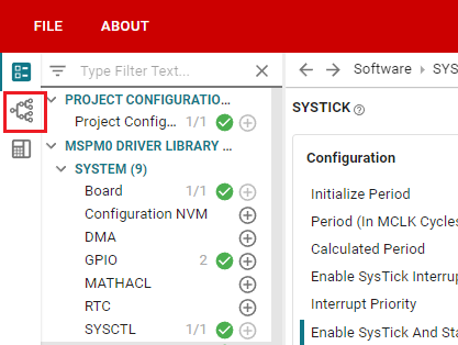
Click the second icon on the far left of the SYSCONFIG interface to open the clock tree.
Open the MFCLK switch in the clock tree, at the position shown in the figure below. Click the option block on the SYSOSC_4M branch to enable MFCLK clock. When 4.0000Mhz appears on the right, the setup is complete.
3. Serial Parameter Configuration
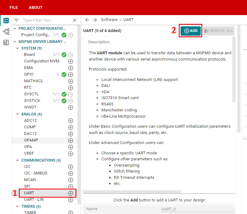
In SYSCONFIG, select MCU peripherals on the left, find the UART option and click to enter. Click ADD in UART to add a serial peripheral group.
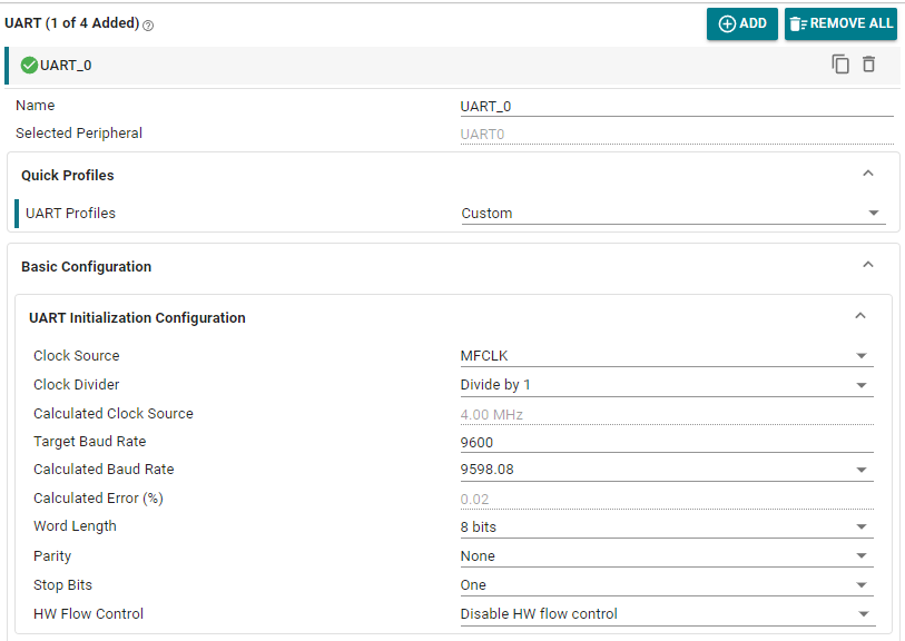
Basic Configuration: Custom serial name, set to UART_0. Clock Source set to MFCLK. Clock Divider set to Divide by 1. The software will automatically calculate the clock source frequency. Configure with baud rate 9600, data bits 8, stop bits 1, parity none, no hardware flow control.
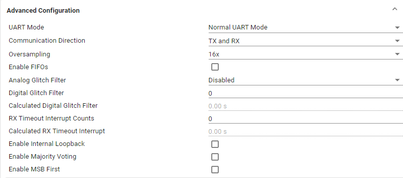
Advanced Configuration: Use default options. The oversampling options are 3, 8, 16. Usually 3 or 8 is sufficient. If the clock deviation is large or the clock speed is too fast causing abnormal baud rate divider calculation, select 16. As long as sysconfig does not report an error. Here our serial clock frequency is 4MHz, so we select 16.
Interrupt Configuration: This case uses interrupt-based serial reception. Whenever a byte is received, it will enter the receive interrupt.

Pin Configuration: According to the schematic, PA10 is TX, PA11 is RX, which is serial port 0.

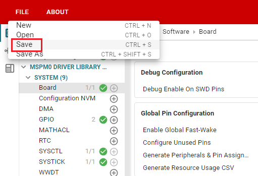
Click SAVE to save the SYSCONFIG configuration, then close SYSCONFIG and return to KEIL.
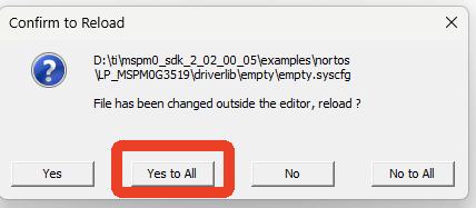
Select Yes to All in the popup.
We also need to confirm whether ti_msp_dl_config.c and ti_msp_dl_config.h files are updated. Simply compile, and the compilation will automatically update to KEIL. If not updated, we can also copy the file content from SYSCONFIG.
4. Write Program
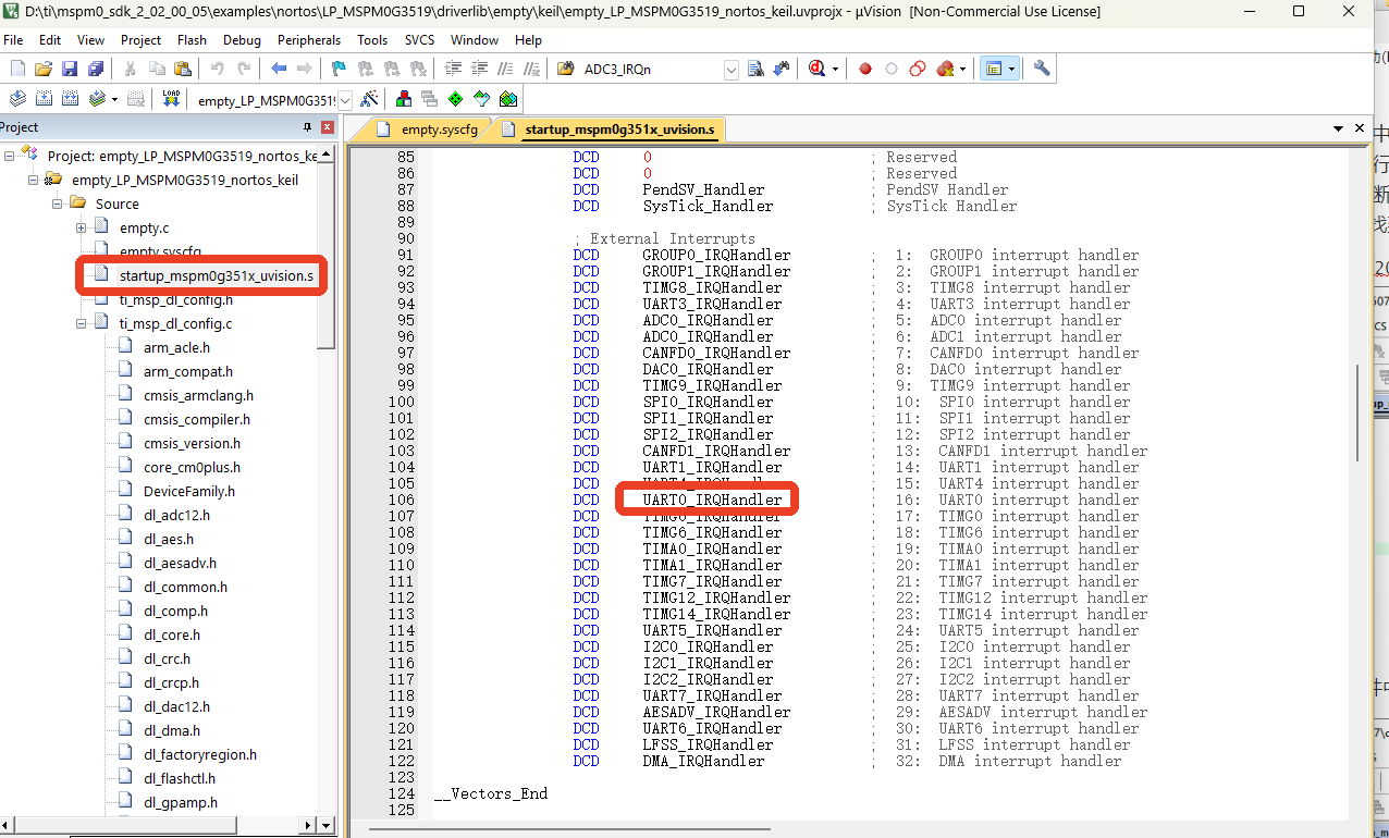
After configuring the serial port, we also need to manually write the serial interrupt service function. Because we enabled the serial receive interrupt, when the serial port receives data, it triggers an interrupt, and the interrupt triggers the execution of the interrupt service function. The interrupt service function name for each interrupt is usually fixed and cannot be modified arbitrarily; otherwise, you will not be able to correctly enter the interrupt service function. The specific name of the interrupt service function can be found in the project's startup_mspm0g350x_uvision.s file, which lists the interrupt service function names for each interrupt source.
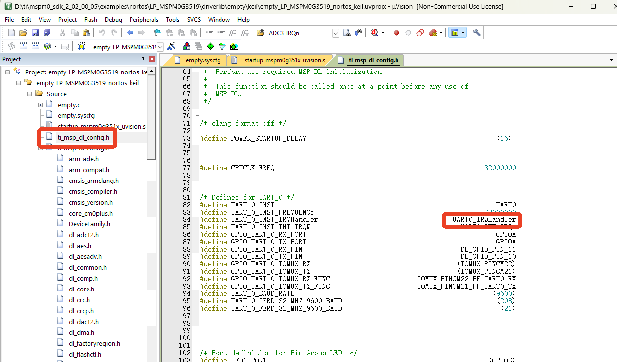
You can also see the macro definition for serial port 0 interrupt service function in the generated ti_msp_dl_config.h file.
So in the empty.c file, write the following code
x#include "ti_msp_dl_config.h"
volatile unsigned int delay_times = 0;volatile unsigned char uart_data = 0;
void delay_ms(unsigned int ms);void uart0_send_char(char ch);void uart0_send_string(char* str);
int main(void){ SYSCFG_DL_init(); // Clear the serial port interrupt flag NVIC_ClearPendingIRQ(UART_0_INST_INT_IRQN); // Enable serial port interrupt NVIC_EnableIRQ(UART_0_INST_INT_IRQN);
while (1) { //LED pin outputs high level DL_GPIO_setPins(LED1_PORT, LED1_PIN_2_PIN); delay_ms(500); //LED pin outputs low level DL_GPIO_clearPins(LED1_PORT, LED1_PIN_2_PIN); delay_ms(500); }}
//Accurate ms delay with tick timervoid delay_ms(unsigned int ms){ delay_times = ms; while( delay_times != 0 );}//Send a single character through the serial portvoid uart0_send_char(char ch){ // Wait when serial port 0 is busy, and send the incoming characters when it is not busy while( DL_UART_isBusy(UART_0_INST) == true ); // Send a single character DL_UART_Main_transmitData(UART_0_INST, ch);}//Send string via serial portvoid uart0_send_string(char* str){ // The current string address is not at the end and the string first address is not empty while(*str!=0&&str!=0) { // Send the characters in the first address of the string, and increment the first address after sending. uart0_send_char(*str++); }}
//Tick timer interrupt service functionvoid SysTick_Handler(void){ if( delay_times != 0 ) { delay_times--; }}
//Serial port interrupt service functionvoid UART_0_INST_IRQHandler(void){ // If a serial port interrupt occurs switch( DL_UART_getPendingInterrupt(UART_0_INST) ) { case DL_UART_IIDX_RX:// If it is a receive interrupt // The data sent is saved in the variable uart_data = DL_UART_Main_receiveData(UART_0_INST); // Send the saved data again uart0_send_char(uart_data); break;
default:// Other serial port interrupts break; }}5. Compile
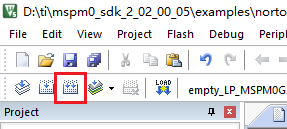
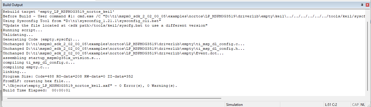
Click the Rebuild icon. The following prompt indicates compilation is complete with no errors.
4. Program Analysis
empty.c
xxxxxxxxxxint main(void){    SYSCFG_DL_init();    // Clear the serial port interrupt flag    NVIC_ClearPendingIRQ(UART_0_INST_INT_IRQN);    // Enable serial port interrupt    NVIC_EnableIRQ(UART_0_INST_INT_IRQN);
    while (1)    {        //LED pin outputs high level        DL_GPIO_setPins(LED1_PORT, LED1_PIN_2_PIN);        delay_ms(500);        //LED pin outputs low level        DL_GPIO_clearPins(LED1_PORT, LED1_PIN_2_PIN);        delay_ms(500);    }}
Serial interrupts must be manually enabled. The function NVIC_EnableIRQ specifies enabling a specific interrupt. The interrupt flag must be cleared first before enabling, otherwise it will automatically enter the interrupt after enabling.
xxxxxxxxxx//Send a single character through the serial portvoid uart0_send_char(char ch){ // Wait when serial port 0 is busy, and send the incoming characters when it is not busy while( DL_UART_isBusy(UART_0_INST) == true ); // Send a single character DL_UART_Main_transmitData(UART_0_INST, ch);}//Send string via serial portvoid uart0_send_string(char* str){ // The current string address is not at the end and the string first address is not empty while(*str!=0&&str!=0) { // Send the characters in the first address of the string, and increment the first address after sending. uart0_send_char(*str++); }}Define two functions. The uart0_send_char function sends a single character via serial port. The uart0_send_string function sends a string via serial port.
xxxxxxxxxx//Serial port interrupt service functionvoid UART_0_INST_IRQHandler(void){    // If a serial port interrupt occurs    switch( DL_UART_getPendingInterrupt(UART_0_INST) )    {        case DL_UART_IIDX_RX:// If it is a receive interrupt            // The data sent is saved in the variable            uart_data = DL_UART_Main_receiveData(UART_0_INST);            // Send the saved data again            uart0_send_char(uart_data);            break;
        default:// Other serial port interrupts            break;    }}
The UART_0_INST_IRQHandler function implements receiving serial data and echoing it back. Through DL_UART_getPendingInterrupt(), it gets the current UART0 interrupt type. If data is received triggering the UART interrupt, the received data is saved in the variable, then sent back out.
5. Experimental Phenomena
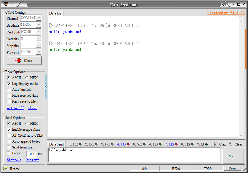
After the program is downloaded, you can send data to the development board through the serial debugging assistant and see the development board return the data.