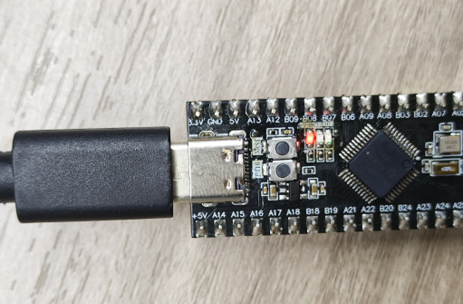
Welcome to MSPM0G3519 Development Board repository
3. Button Control
Button Control
Button Control1. Learning Objectives2. Hardware SetupIndependent Button PrincipleButton Debouncing3. Experiment Steps1. Open SYSCONFIG Configuration Tool2. Configure Pin Mode3. Write Program4. Compile4. Program Analysis5. Experimental Phenomena
1. Learning Objectives
Learn the basic working principle of buttons on the MSPM0G3519 motherboard.
Use the onboard button to control the onboard LED light on/off.
2. Hardware Setup
Independent Button Principle
Independent buttons are typically implemented through mechanical switches. Their hardware structure consists of a button, connecting wires, and pull-up/pull-down resistors. When the button is closed, the circuit is connected and the signal level changes; when the button is released, the circuit is disconnected and the signal returns to its initial state.
Button Debouncing
The mechanical elasticity of buttons causes the signal to jump multiple times in a short period when closing or releasing. This is called button bouncing. It is usually eliminated through software delay debouncing or hardware RC filter circuit.
This course does not require additional hardware. You can directly use the onboard function button on the MSPM0G3519 development board.
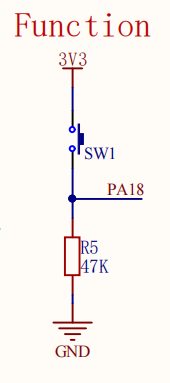
In the development board schematic, the PA18 pin is connected to a button. One end of the button is connected to high level (3.3V), and the other end is connected to the GPIO pin, while also being connected to ground through a 47kΩ pull-down resistor R5. When the button is not pressed, the PA18 pin level is pulled low to 0V due to the pull-down resistor. When the button is pressed, the PA18 pin is directly connected to high level 3.3V, thereby achieving high and low level changes. The development board determines whether the button is pressed by detecting the level status of the PA18 pin. This design is simple and stable, effectively avoiding signal interference caused by floating pins.
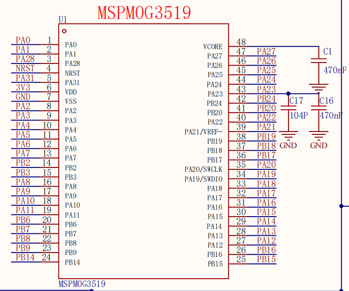
MSPM0G3519 Main Control Diagram
Button Part Schematic
3. Experiment Steps
In microcontrollers, pin input mode means configuring a certain pin as an input function to receive changes in external signals. The working principle of buttons is based on this: by setting the pin connected to the button as input mode, the microcontroller can detect level changes on the pin. When the button is not pressed, the pin level remains low; when the button is pressed, the pin level becomes high. This high and low level change is the embodiment of the button input signal, and it is also the basis for the microcontroller to determine button status. Therefore, the process of receiving external signals is actually the process of detecting button high and low level changes through input mode.
1. Open SYSCONFIG Configuration Tool
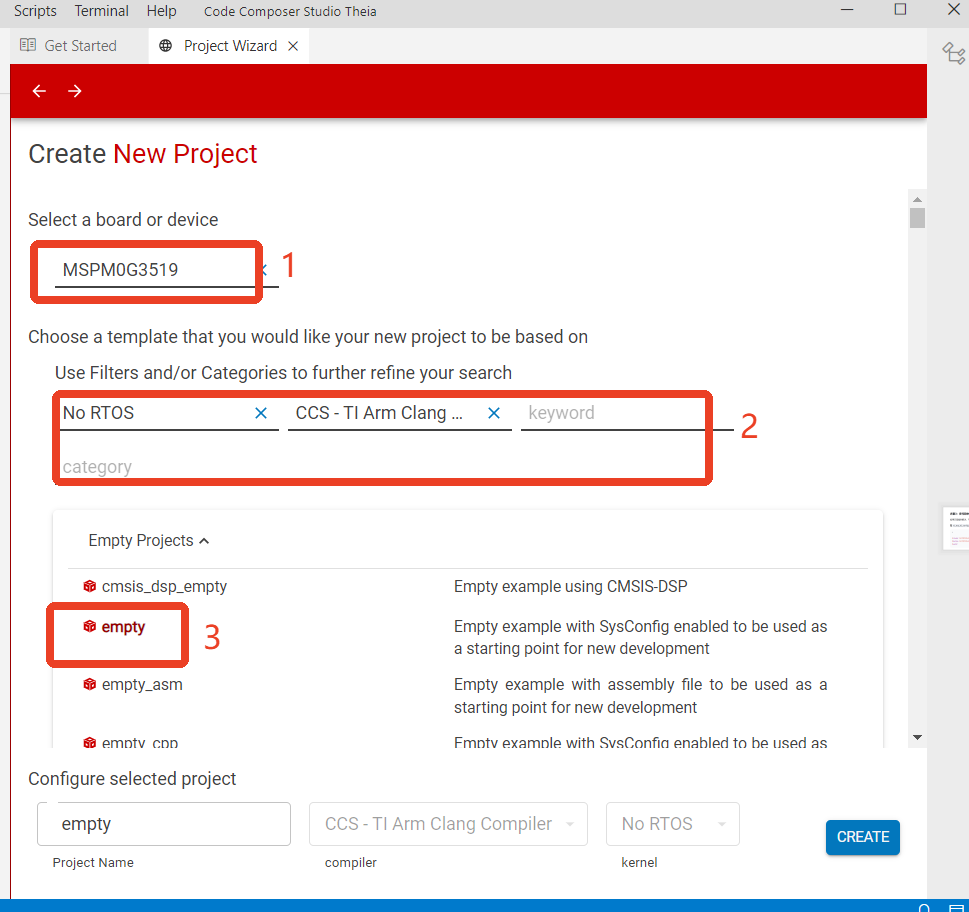
Create a new empty project empty in CCS.
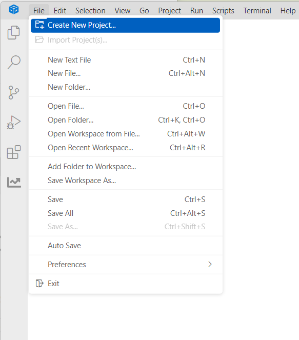
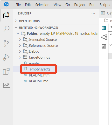
Find and open the empty.syscfg file in the left workspace of CCS.
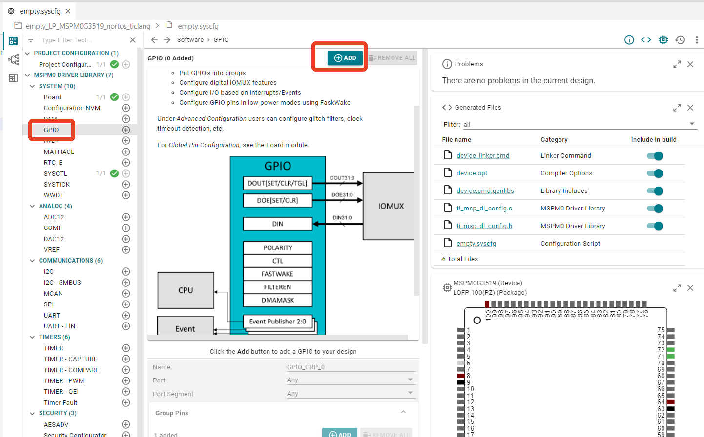
In SYSCONFIG, select MCU peripherals on the left, find the GPIO option and click to enter. Click ADD in GPIO to add two groups of pin peripherals: one for LED pins and one for button pins. For LED pin configuration, refer to the previous Turn On LED course. Only button pin configuration is explained here.
2. Configure Pin Mode
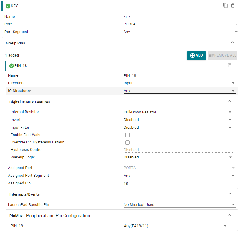
Configure pin parameters, name the GPIO instance KEY. Since it is connected to PA18, Port selects PORTA.
Set the pin name to PIN_18, set to input mode Input. Internal Resistor sets to pull-down resistor Pull-Down Resistor. Assigned Pin sets the controlled pin to 18.
Save the configuration in the .syscfg file using the shortcut key Ctrl+S.
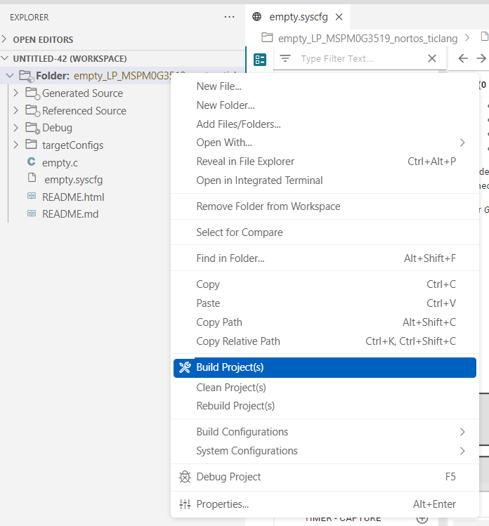
After saving, compile.
3. Write Program
In the empty.c file, write the following code
x#include "ti_msp_dl_config.h"
int main(void){
SYSCFG_DL_init();
while (1) { // If the pin value read is greater than 0, it means that the PA18 pin is high level. if( DL_GPIO_readPins(KEY_PORT, KEY_PIN_18_PIN) > 0 ) { DL_GPIO_setPins(LED1_PORT,LED1_PIN_2_PIN); //LED control output high level } else// If the PA18 pin is low { DL_GPIO_clearPins(LED1_PORT,LED1_PIN_2_PIN);//LED control output low level } }}4. Compile
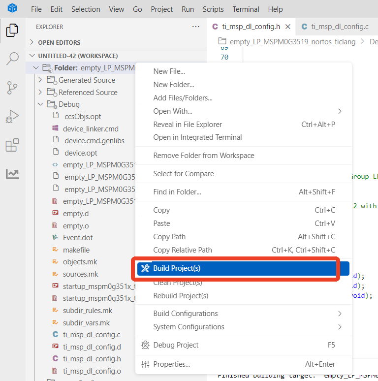
Compilation was successful. You can now download the program to the development board.
4. Program Analysis
empty.c
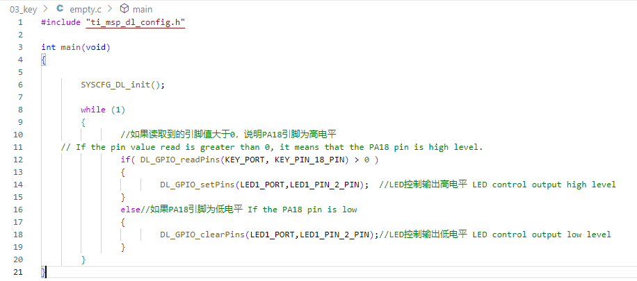
uint32_t DL_GPIO_readPins(GPIO_Regs* gpio, uint32_t pins) is used to read the level status of specified GPIO pins. By reading the value of the GPIO register, it obtains the status of the specified pin. Input the GPIO port and pin number to read, and return the level status of that pin.
gpio: The GPIO port to read.
pins: The pin number to read.
This code controls the LED by continuously detecting the level status of pin PA18 (button input pin) to control the output level of LED1_PIN_2 (LED control pin). When PA18 is high, the LED turns on (LED pin outputs high level); when PA18 is low, the LED turns off (LED pin outputs low level).
5. Experimental Phenomena
After the program is downloaded, you can control the LED light on/off with the button. Press the button, the LED turns on; release the button, the LED turns off.