Welcome to MSPM0G3519 Development Board repository
4. External Interruption
External Interrupt Experiment
External Interrupt Experiment1. Learning Objectives2. External InterruptExternal Interrupt Advantages and Functions3. Hardware Setup4. Experiment Steps1. Open SYSCONFIG Configuration Tool2. Configure Pin Mode3. Write Program4. Compile4. Program Analysis5. Experimental Phenomena
1. Learning Objectives
Learn about external interrupt knowledge on the MSPM0G3519 motherboard.
Use the onboard button to control the onboard LED light on/off.
2. External Interrupt
An interrupt is when the CPU, while executing a program, has another event that needs to occupy the CPU. After receiving this interrupt request, the CPU pauses the execution of the original program to execute the interrupt function. After the interrupt function completes, it continues to execute from where it left off in the original program.
External Interrupt refers to an interrupt triggered by external hardware events (usually signals from outside the microcontroller). This interrupt can interrupt the current program execution flow of the microcontroller, allowing it to respond quickly to external hardware events.
External interrupts are usually associated with specific pins (GPIO pins), such as buttons, sensor signals, timer signals, etc. These pins are typically configured to detect specific signal changes (such as rising edge, falling edge, or level changes), thereby triggering an interrupt.
External Interrupt Advantages and Functions
Advantages:
Fast Response: External interrupts can respond immediately when a triggering event occurs, without polling signals.
Resource Saving: No need to continuously detect signal status in the main loop, saving CPU resources.
Improved Real-time Performance: The interrupt mechanism ensures timely processing of critical events, thereby improving system real-time performance.
Functions:
Fast Response to External Events: Can immediately interrupt the current program execution and quickly process the event when hardware events occur, without polling signal status. Avoids the program polling for events, greatly saving CPU resources and improving the system's response speed to external events.
Improved System Real-time Performance: In scenarios requiring real-time response, external interrupts ensure critical events are processed in a timely manner without waiting for the system main program to complete its current task, thereby improving system real-time performance.
Reduced Main Program Burden: External interrupts separate tasks related to external events from the main program, avoiding polling signal status in the main program and improving main program execution efficiency, allowing the main program to focus on core tasks.
Core of Event-Driven Systems: Can implement efficient event-driven mechanisms and reduce system complexity.
Hardware Interaction and Control: External interrupts enable microcontrollers to real-time process and respond to external hardware signals, ensuring the system operates normally.
Data Acquisition and Processing: In many real-time data acquisition systems, external interrupts are used to trigger data acquisition or processing.
Low-Power Scenario Triggering Mechanism: Through external interrupts, efficient low-power design can be achieved, allowing the system to remain in sleep state when not working and only run when necessary.
System Security Assurance: Timately processing security-related events to ensure system reliability and safety.
3. Hardware Setup
This course does not require additional hardware. You can directly use the onboard function button on the MSPM0G3519 development board.
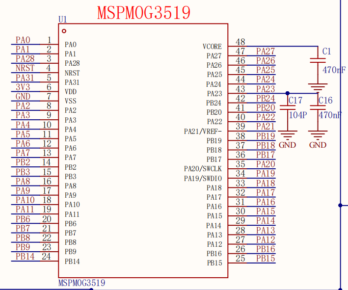
MSPM0G3519 Main Control Diagram
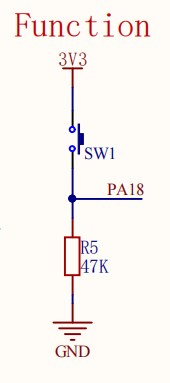
Button Part Schematic
4. Experiment Steps
In this course, the PA18 button will be used to trigger LED1 on PB2 to light up and go out. In software, CPU interrupt mode is used. For LED1 PB2 pin configuration, please refer to the Turn On LED Light course.
1. Open SYSCONFIG Configuration Tool
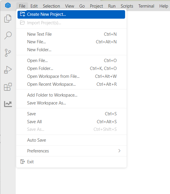
Create a new empty project empty in CCS.
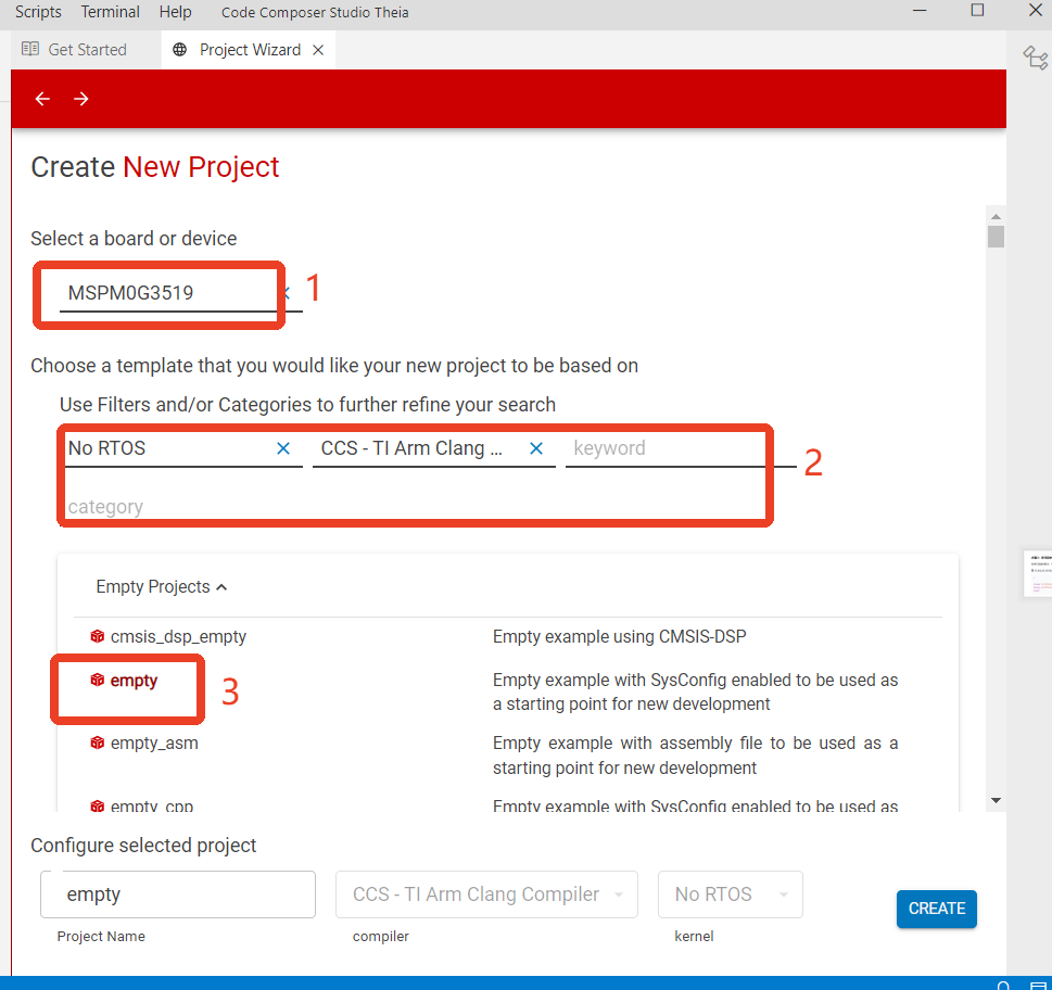
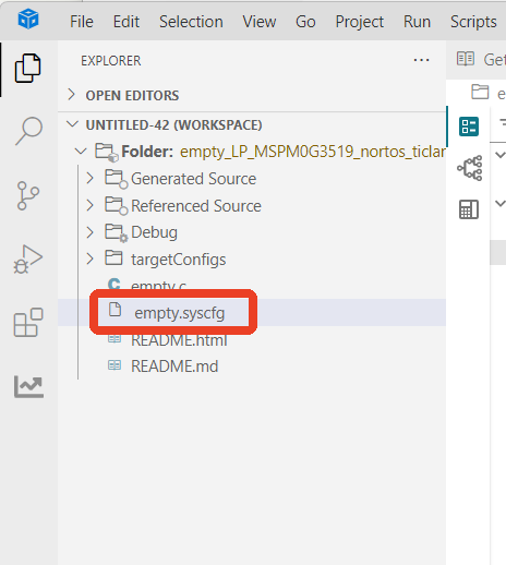
Find and open the empty.syscfg file in the left workspace of CCS.
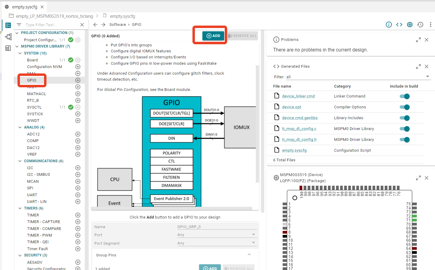
In SYSCONFIG, select MCU peripherals on the left, find the GPIO option and click to enter. Click ADD in GPIO to add two groups of pin peripherals: one for LED pins and one for button pins. For LED pin configuration, refer to the previous Turn On LED course. Only button pin configuration is explained here.
2. Configure Pin Mode
Configure pin parameters, name the GPIO instance KEY. Since it is connected to PA18, Port selects PORTA.
Set the pin name to PIN_18, set to input mode Input. Internal Resistor sets to pull-down resistor Pull-Down Resistor. Assigned Pin sets the controlled pin to 18.
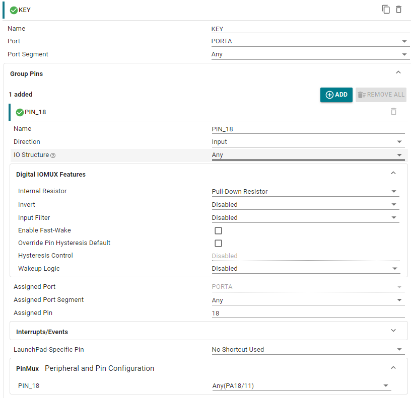
Configure pin external interrupt. All GPIOA ports brought out from the chip can have external interrupt functionality set.
Enable Interrupts enables the interrupt. Interrupt Priority sets the interrupt priority to default. When multiple interrupts trigger simultaneously, the chip's default priority rules are followed.
Trigger Polarity sets the interrupt trigger mode to rising edge trigger. When the button is pressed, the GPIO pin level changes from low (0) to high (1). This process is called a rising edge. This means the external interrupt will be triggered when the pin state changes from low to high.
Event Publishing Channel does not enable the event publishing channel. The event publishing channel is a mechanism for publishing interrupt events to specified channels. Other peripherals can respond by subscribing to events on the channel.

Save the configuration in the .syscfg file using the shortcut key Ctrl+S.
3. Write Program
According to the MSPM0G series user manual, after GPIO interrupts are triggered, they are all published to the bus through the GRP1 line. After the bus recognizes it, it enters the interrupt service function to execute the content.
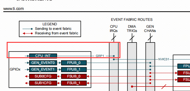
After configuring the pin interrupt, we also need to manually write the external interrupt service function. Because we enabled the pin falling edge interrupt, when our button goes from pressed to released, the generated falling edge will trigger an interrupt, and after triggering, it will execute the interrupt service function. The interrupt service function name for each interrupt is usually fixed and cannot be modified arbitrarily; otherwise, you will not be able to correctly enter the interrupt service function. The interrupt service function name is GROUP1_IRQHandler.
In the empty.c file, write the following code
x#include "ti_msp_dl_config.h"
int main(void){ SYSCFG_DL_init(); NVIC_EnableIRQ(KEY_INT_IRQN);//Enable GPIOA port interrupt for button pin
while (1) {
}}
void GROUP1_IRQHandler(void)//Interrupt service function of Group1{ // Read the interrupt register of Group1 and clear the interrupt flag switch( DL_Interrupt_getPendingGroup(DL_INTERRUPT_GROUP_1) ) { // Check if it is the GPIOA port interrupt of KEY, note that it is INT_IIDX, not PIN_18_IIDX case KEY_INT_IIDX: // If the button is pressed, it becomes high level if( DL_GPIO_readPins(KEY_PORT, KEY_PIN_18_PIN) > 0 ) { // Set LED pin state toggle DL_GPIO_togglePins(LED1_PORT, LED1_PIN_2_PIN); } break; }}4. Compile
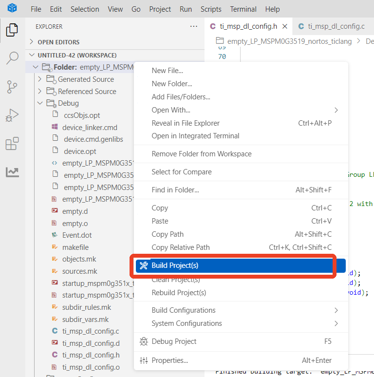
Compilation was successful. You can now download the program to the development board.
4. Program Analysis
empty.c
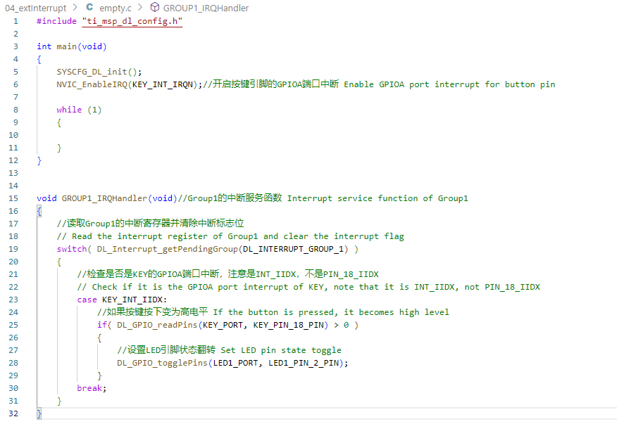
uint32_t DL_Interrupt_getPendingGroup(DL_INTERRUPT_GROUP group) is used to get the highest priority pending interrupt index in the specified interrupt group.
group: An enumeration type DL_INTERRUPT_GROUP used to specify which interrupt group to check.
This code implements a basic interrupt service function, mainly using button-triggered interrupts to control the status of an LED.
After the main() function initializes, it enables the GPIOA port interrupt for the button. The GROUP1_IRQHandler() interrupt service function gets the highest priority pending flag in Group1, checks if a button interrupt occurred, then calls DL_GPIO_readPins(KEY_PORT, KEY_PIN_18_PIN) to read the button pin level change. If it becomes high level, the LED pin state toggles.
5. Experimental Phenomena
After the program is downloaded, you can control the LED light status with the button. Press once, the LED turns on; press again, the LED turns off.