Welcome to MSPM0G3519 Development Board repository
10. Get MPU6050 data (I2C)
Get MPU6050 Data (I2C)
Get MPU6050 Data (I2C)1. Learning ObjectivesI2C IntroductionI2C Basic Parameters2. Hardware Setup3. Experiment Steps1. Open SYSCONFIG Configuration Tool2. Pin Parameter Configuration3. Serial Parameter Configuration4. I2C Protocol Usage5. Write Program6. Compile4. Program Analysis5. Experimental Phenomena
1. Learning Objectives
Learn basic I2C communication knowledge.
Get MPU6050 data.
I2C Introduction
IIC bus is a bidirectional two-wire serial bus that provides communication lines between integrated circuits. Its meaning is the protocol for completing information exchange between integrated circuits or functional units.
The IIC module receives and transmits data, converting data from serial to parallel or parallel to serial. It can enable or disable interrupts. The interface connects to the IIC bus through the data pin (SDA) and clock pin (SCL). It allows connection to standard (up to 100kHz) or fast (up to 400kHz) IIC bus. (Data line SDA and clock SCL constitute the serial bus, can send and receive data).
The IIC bus has three types of signals during data transmission: start signal (START), stop (end) signal (STOP), and acknowledge signal (ACK). Secondly, it is in idle state when no data is being transmitted.
I2C Basic Parameters
Rate: I2C bus has two transmission modes: standard mode (100 kbit/s) and fast mode (400 kbit/s). There are also faster extended mode and high-speed mode available.
Device Address: Each device has a unique 7-bit or 10-bit address. You can determine who to communicate with through address selection.
Bus State: I2C bus has five states: idle state, start signal, end signal, acknowledge signal, and data transmission.
Data Format: I2C bus has two data formats: standard format and fast format. Standard format is 8-bit data byte plus 1-bit ack/nack bit. Fast format allows two bytes to be transmitted simultaneously.
Since SCL and SDA lines are bidirectional, they may also have level errors due to external reasons (such as capacitance in the circuit), leading to communication errors. Therefore, in IIC bus, pull-up resistors are usually used to ensure the signal line is at high level in the idle state.
2. Hardware Setup
MSPM0G series I2C supports master-slave mode, has 7-bit address bits configurable, supports 100kbps, 400kbps, 1Mbps I2C standard transmission rates, and supports SMBUS. Whether as master or slave, both sending and receiving have independent 8-byte FIFO. MSPM0 I2C has 8-byte FIFO, generates independent interrupts for controller and target modes, and supports DMA.
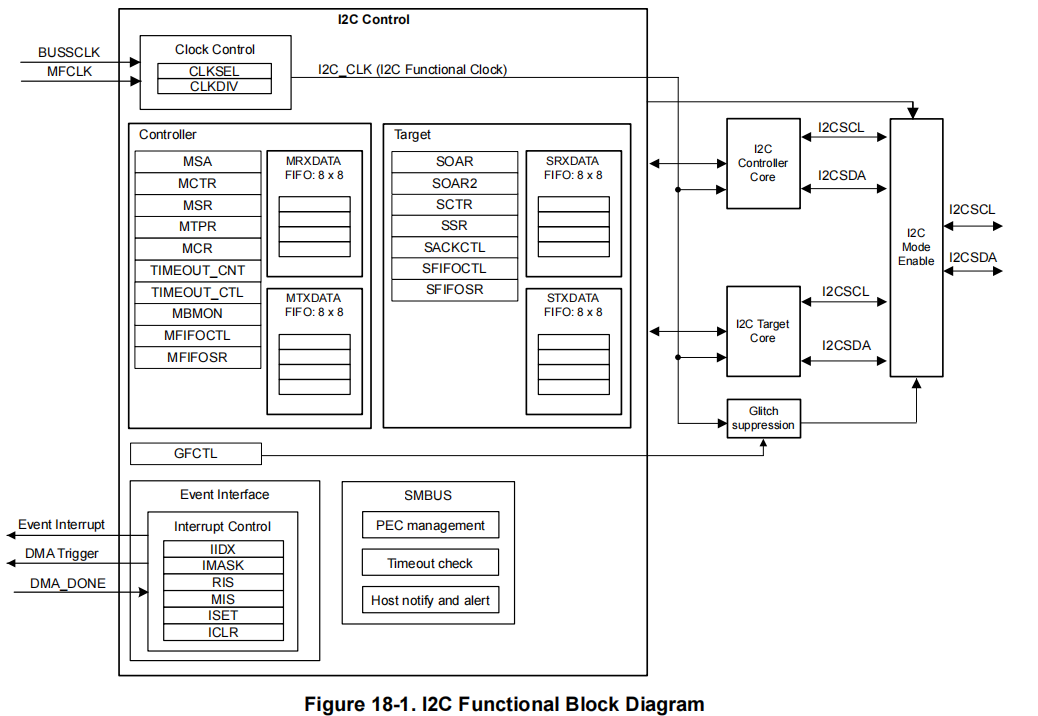
Software I2C refers to implementing the I2C communication protocol by writing code in the program. It uses general-purpose input/output (GPIO) pins to simulate I2C's data line (SDA) and clock line (SCL), controlling pin level changes through software to transmit data and generate timing signals. Compared with hardware I2C, the advantage of software I2C is that it does not require specific hardware support and can be implemented on any microcontroller that supports GPIO functions. It uses the microcontroller's general IO pins to implement the I2C communication protocol.
Hardware I2C refers to handling I2C communication protocol through a dedicated hardware module. Most modern microcontrollers and some external devices have integrated hardware I2C modules. These hardware modules are responsible for handling I2C communication details, including generating correct timing signals, automatically handling signal conflicts, data transmission, and error detection. You can directly use hardware pin connections without writing timing code.
This experiment uses software I2C to read data from the MPU6050 module.
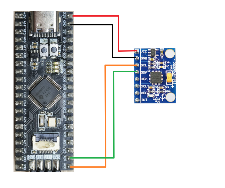
Hardware Connection
| MSPM0G3519 | MPU6050 |
|---|---|
| PA0 | SCL |
| PA1 | SDA |
| 3V3 | VCC |
| GND | GND |
3. Experiment Steps
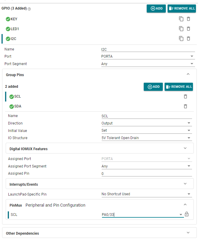
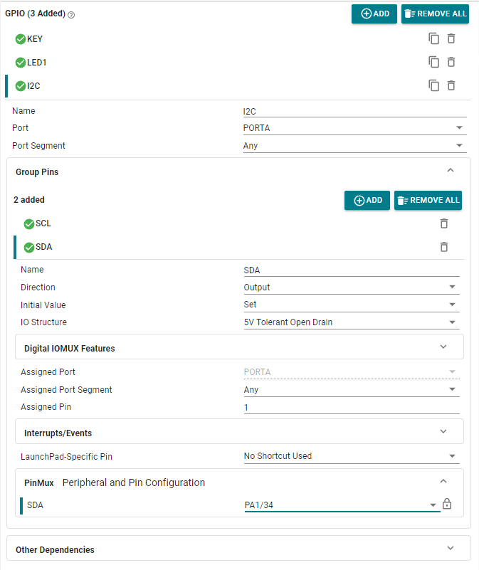
This course configures PA0 and PA1 pins as SCL and SDA to read data from the MPU6050 six-axis sensor module.
1. Open SYSCONFIG Configuration Tool
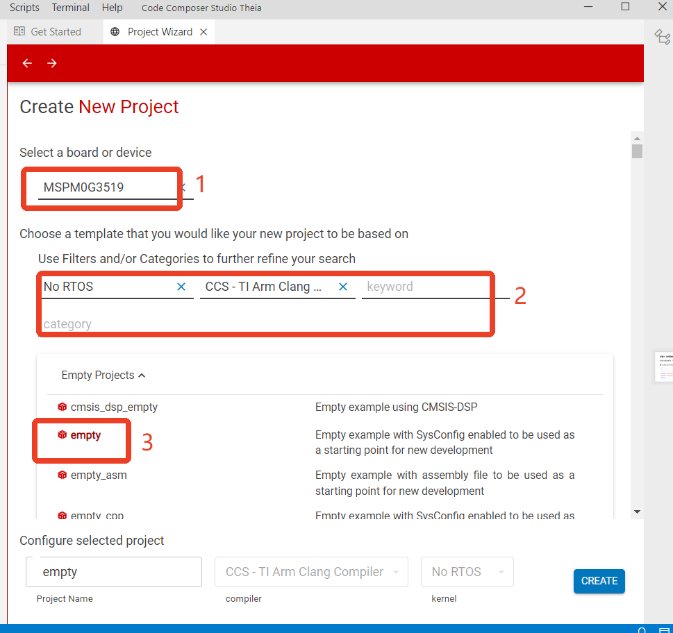
Create a new empty project empty in CCS.
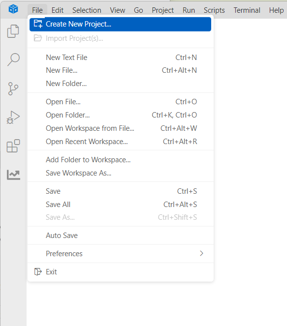
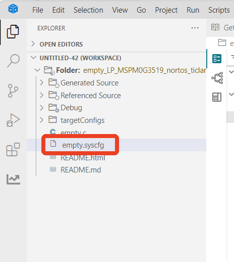
Find and open the empty.syscfg file in the left workspace of CCS.
2. Pin Parameter Configuration
LED light and button pin configuration can refer to previous courses. Here only I2C related pin configuration is shown.
SCL:
SDA:
3. Serial Parameter Configuration
The not shown part is the default option.
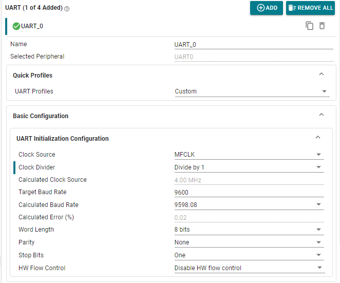
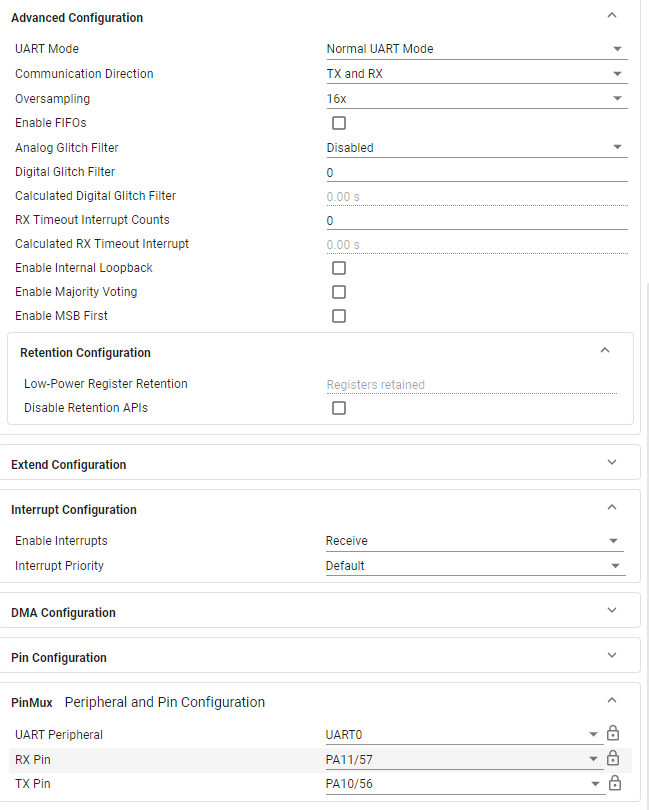
Save the configuration in the .syscfg file using the shortcut key Ctrl+S.
4. I2C Protocol Usage
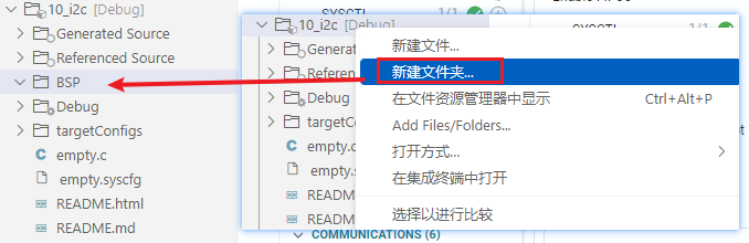
We create a new folder in the project folder: BSP.
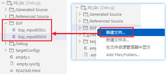
In the BSP folder, create two new files: bsp_mpu6050.c and bsp_mpu6050.h.
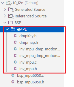
Then put the MPU6050 gyroscope and accelerometer driver design into the newly created eMPL folder.
Update header file paths.
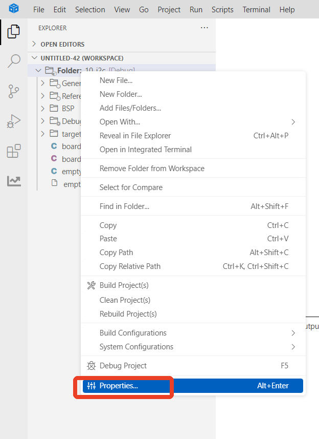
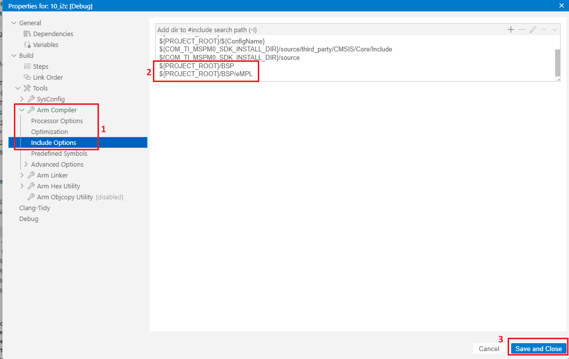
${PROJECT_ROOT}/BSP path description
${PROJECT_ROOT} represents the current project path.
/BSP represents the Hardware folder under the current project path.
5. Write Program
When implementing I2C communication in software, you need to select appropriate pins for data line (SDA) and clock line (SCL). Usually, any programmable GPIO pin can be selected as the software I2C pin. For software I2C, you need at least two pins for data line (SDA) and clock line (SCL), and ensure these pins can meet the timing requirements of the I2C communication protocol. The following are general pin descriptions:
Data line (SDA): Pin for transmitting data. In software I2C, this pin needs to be set to output mode (for master device sending data) and input mode (for master device receiving data). During communication, data transmission is achieved by controlling data line level changes.
Clock line (SCL): Pin for controlling the clock signal for data transmission. In software I2C, this pin needs to be set to output mode. Clock pulses are generated by controlling clock line level changes to control data line transmission. Note that when selecting appropriate pins, consider the following aspects:
Support input/output configuration: Pins need to support being configured as input or output mode in software and can be dynamically switched through the program.
Hardware limitations and conflicts: Ensure the selected pins are not assigned to other hardware functions or peripherals to avoid conflicts.
Electrical characteristics: Pin electrical characteristics should meet I2C bus standard requirements, such as correct levels and drive capability.
Note that software I2C implementation requires more program code and computation. Compared with hardware I2C, software I2C is more sensitive to processor performance and timing control. Therefore, when selecting pins, you also need to consider processor performance and programmable performance. To ensure code maintainability and portability, related functions are macro-defined here.
SDA pin and SCL pin macro definitions are as follows:
bsp_mpu6050.h
x#ifndef _BSP_MPU6050_H_#define _BSP_MPU6050_H_
#include "board.h"
// Set SDA output mode#define SDA_OUT() { \ DL_GPIO_initDigitalOutput(I2C_SDA_IOMUX); \ DL_GPIO_setPins(I2C_PORT, I2C_SDA_PIN); \ DL_GPIO_enableOutput(I2C_PORT, I2C_SDA_PIN); \ }// Set SDA input mode#define SDA_IN() { DL_GPIO_initDigitalInput(I2C_SDA_IOMUX); }
// Get the level change of the SDA pin#define SDA_GET() ( ( ( DL_GPIO_readPins(I2C_PORT,I2C_SDA_PIN) & I2C_SDA_PIN ) > 0 ) ? 1 : 0 )// SDA and SCL output#define SDA(x) ( (x) ? (DL_GPIO_setPins(I2C_PORT,I2C_SDA_PIN)) : (DL_GPIO_clearPins(I2C_PORT,I2C_SDA_PIN)) )#define SCL(x) ( (x) ? (DL_GPIO_setPins(I2C_PORT,I2C_SCL_PIN)) : (DL_GPIO_clearPins(I2C_PORT,I2C_SCL_PIN)) )
// AD0 of MPU6050 is the IIC address pin. If it is grounded, the IIC address is 0x68. If it is connected to VCC, the IIC address is 0x69.
#define MPU6050_RA_SMPLRT_DIV 0x19 // Gyro sampling rate address#define MPU6050_RA_CONFIG 0x1A // Set digital low-pass filter address#define MPU6050_RA_GYRO_CONFIG 0x1B // Gyro configuration register#define MPU6050_RA_ACCEL_CONFIG 0x1C // Acceleration sensor configuration register#define MPU_INT_EN_REG 0X38 // Interrupt enable register#define MPU_USER_CTRL_REG 0X6A // User control register#define MPU_FIFO_EN_REG 0X23 // FIFO enable register#define MPU_PWR_MGMT2_REG 0X6C // Power management register 2#define MPU_GYRO_CFG_REG 0X1B // Gyroscope configuration register#define MPU_ACCEL_CFG_REG 0X1C // Accelerometer configuration register#define MPU_CFG_REG 0X1A // Configuration register#define MPU_SAMPLE_RATE_REG 0X19 // Sampling frequency divider#define MPU_INTBP_CFG_REG 0X37 // Interrupt/bypass setting register
#define MPU6050_RA_PWR_MGMT_1 0x6B#define MPU6050_RA_PWR_MGMT_2 0x6C
#define MPU6050_WHO_AM_I 0x75#define MPU6050_SMPLRT_DIV 0 //8000Hz#define MPU6050_DLPF_CFG 0#define MPU6050_GYRO_OUT 0x43 // MPU6050 gyroscope data register address#define MPU6050_ACC_OUT 0x3B // MPU6050 acceleration data register address
#define MPU6050_RA_TEMP_OUT_H 0x41 // High temperature#define MPU6050_RA_TEMP_OUT_L 0x42 // Low temperature
#define MPU_ACCEL_XOUTH_REG 0X3B // Acceleration value, X-axis high 8-bit register#define MPU_ACCEL_XOUTL_REG 0X3C // Acceleration value, X-axis low 8-bit register#define MPU_ACCEL_YOUTH_REG 0X3D // Acceleration value, Y-axis high 8-bit register#define MPU_ACCEL_YOUTL_REG 0X3E // Acceleration value, Y-axis low 8-bit register#define MPU_ACCEL_ZOUTH_REG 0X3F // Acceleration value, Z-axis high 8-bit register#define MPU_ACCEL_ZOUTL_REG 0X40 // Acceleration value, Z-axis low 8-bit register
#define MPU_TEMP_OUTH_REG 0X41 // Temperature value high eight bits register#define MPU_TEMP_OUTL_REG 0X42 // Temperature value lower 8 bits register
#define MPU_GYRO_XOUTH_REG 0X43 // Gyroscope value, X-axis high 8-bit register#define MPU_GYRO_XOUTL_REG 0X44 // Gyroscope value, X-axis low 8-bit register#define MPU_GYRO_YOUTH_REG 0X45 // Gyroscope value, Y-axis high 8-bit register#define MPU_GYRO_YOUTL_REG 0X46 // Gyroscope value, Y-axis low 8-bit register#define MPU_GYRO_ZOUTH_REG 0X47 // Gyroscope value, Z-axis high 8-bit register#define MPU_GYRO_ZOUTL_REG 0X48 // Gyroscope value, Z-axis low 8-bit register
char MPU6050_WriteReg(uint8_t addr,uint8_t regaddr,uint8_t num,uint8_t *regdata);char MPU6050_ReadData(uint8_t addr, uint8_t regaddr,uint8_t num,uint8_t* Read);
char MPU6050_Init(void);void MPU6050ReadGyro(short *gyroData);void MPU6050ReadAcc(short *accData);float MPU6050_GetTemp(void);uint8_t MPU6050ReadID(void);#endifNext is configuring the I2C timing part:
bsp_mpu6050.c (only partial excerpt shown here, see project source code for details)
xxxxxxxxxx#include "bsp_mpu6050.h"#include "stdio.h"

/****************************************************************** * Function name: IIC_Start * Function description: IIC start timing * Function parameters: None * Function return: None * Author: LC * Remarks: None ******************************************************************/void IIC_Start(void){        SDA_OUT();        SCL(1);        SDA(0);
        SDA(1);        delay_us(5);        SDA(0);        delay_us(5);
        SCL(0);}/****************************************************************** * Function name: IIC_Stop * Function description: IIC stop signal * Function parameters: None * Function return: None * Author: LC * Remarks: None ******************************************************************/void IIC_Stop(void){        SDA_OUT();        SCL(0);        SDA(0);
        SCL(1);        delay_us(5);        SDA(1);        delay_us(5);
}...
Then in the empty.c file, write the following code
xxxxxxxxxx#include "board.h"#include <stdio.h>#include "bsp_mpu6050.h"#include "inv_mpu.h"
char buf[100];  // Defining buffers
int main(void){    // Development board initialization    board_init();
    // Initialize MPU6050    MPU6050_Init();
    uint8_t ret = 1;    float pitch = 0, roll = 0, yaw = 0;  // Euler Angles
    printf("start\r\n");
    // DMP initialization    while (mpu_dmp_init())    {        printf("DMP error\r\n");        delay_ms(200);    }
    printf("Initialization Data Succeed \r\n");
    while (1)    {        // Get Euler angles        if (mpu_dmp_get_data(&pitch, &roll, &yaw) == 0)        {            // Format data and send            sprintf(buf, "pitch = %d, roll = %d, yaw = %d\n", (int)pitch, (int)roll, (int)yaw);            uart0_send_string(buf);  // Serial port sending        }        else        {            // Failed to obtain data            printf("Data get error\r\n");        }
        delay_ms(200);  // Delay, adjusted according to the actual sampling rate    }
}
6. Compile
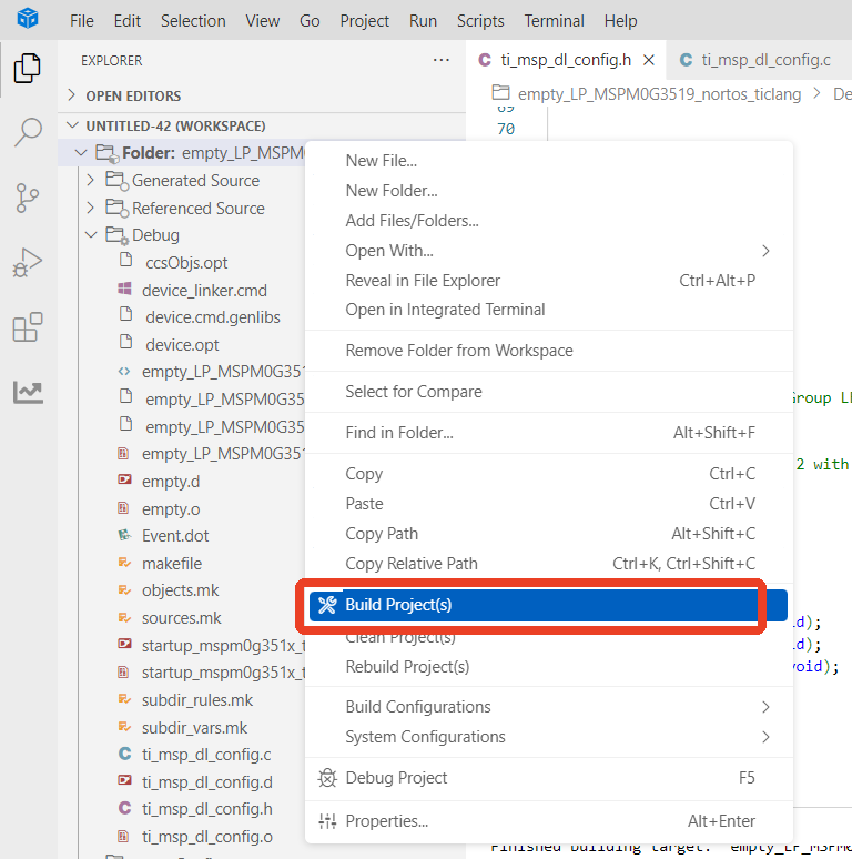
Compilation was successful. You can now download the program to the development board.
4. Program Analysis
inv_mpu.c
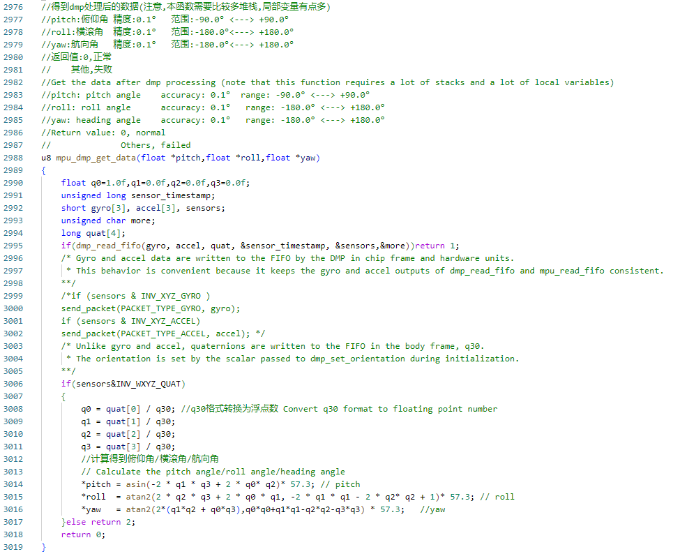
This function reads DMP-processed sensor data (including gyroscope, accelerometer, and quaternion) from MPU6050's FIFO, calculates pitch, roll, and yaw by parsing the quaternion, and returns the results.
empty.c
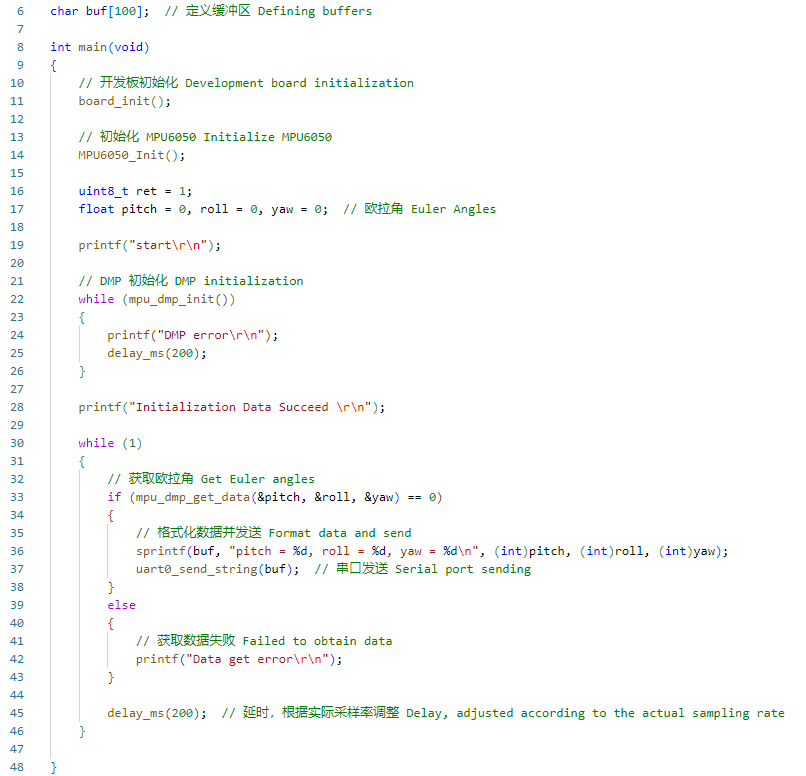
This program obtains attitude data (pitch, roll, yaw) through the MPU6050 sensor and uses DMP (Digital Motion Processor) to calculate Euler angles.
After initializing the development board and MPU6050 sensor, it attempts to initialize the DMP module, retrying if initialization fails.
In the main loop, it continuously acquires sensor Euler angle data, formats it, and sends it through the serial port. If data acquisition fails, it outputs an error message. Data is acquired every 200 milliseconds to ensure appropriate sampling frequency.
5. Experimental Phenomena
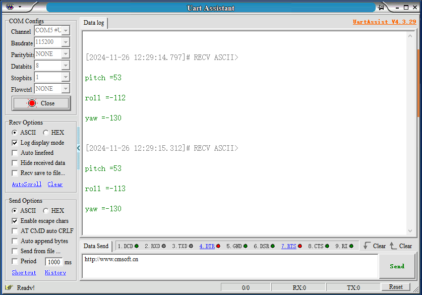
After the program is downloaded, after configuring the serial assistant as shown in the figure below, open the serial port. You can read real-time data from the MPU6050 module.