Welcome to MSPM0G3519 Development Board repository
1. Autonomous Driving Car
Autonomous Driving Car (Question H)
1. Introduction
Please read the "Motor Introduction and Usage" in the Four-Channel Motor Driver Board documentation first to understand the motor parameters, wiring method, and supply voltage you are currently using. This is to avoid damaging the mainboard or motors.
Usage tips: Since the MPU6050 yaw angle easily drifts, or different motors may be used, this project may not run perfectly on the track after burning. You can modify variables based on key points mentioned in the code analysis below, or replace the MPU6050 with other modules.
2. Experiment Preparation
National Competition Chassis V2 Four-Wheel Version, 4*L520 Motors, 12V Lithium Battery, Eight-Channel Line Tracking Module, MPU6050, MSPM0 Robot Expansion Board (optional), MSPM0G3519 Core Board (Yahboom). The sound and light reminders required in Question H are integrated on the MSPM0 Robot Expansion Board (Buzzer PB24) and Yahboom Version MSPM0G3519 Core Board (LED PB2). Users who do not use the MSPM0 Robot Expansion Board need to prepare a buzzer themselves. Also, the competition question selection function button K1 (PA2) is located on the MSPM0 Robot Expansion Board.
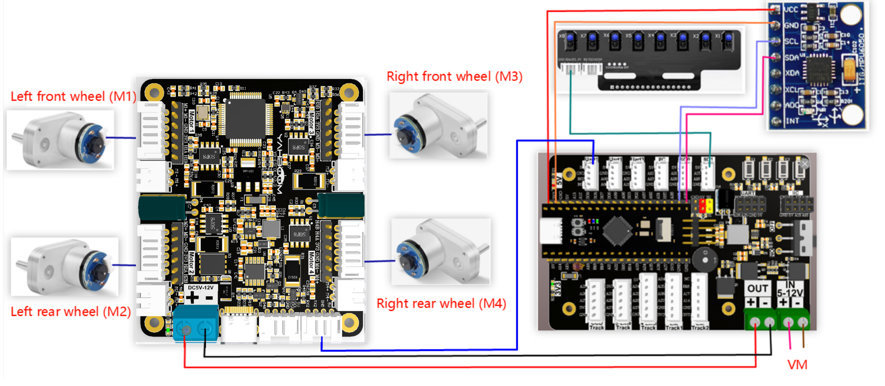
The relationship between the 4 motor interfaces and the car is as follows:
M1 -> Left Front Motor ( car's left front wheel)
M2 -> Left Rear Motor (car's left rear wheel)
M3 -> Right Front Motor (car's right front wheel)
M4 -> Right Rear Motor (car's right rear wheel)
Hardware Wiring:
Using MSPM0 Expansion Board Wiring
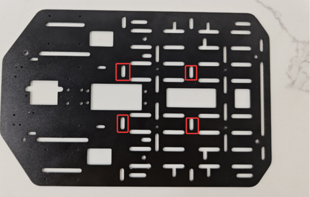
During installation and wiring, if you find the wire length is not enough, you can move the MSPM0 Robot Expansion Board forward a bit for installation, as shown in the figure below.
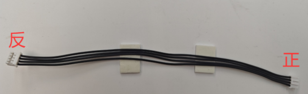
Note: The wire used for the eight-channel line tracking module and the wire connecting the MSPM0 Robot Expansion Board to the four-channel motor driver module is: PH2.0-4pin cable double-ended all-black reverse (200mm). The reverse cable socket direction is shown in the figure below.
Using MSP Core Board Wiring

Wiring Pins:
| Four-Channel Motor Driver Board | MSPM0G3519 |
|---|---|
| RX2 | PB6 |
| TX2 | PB7 |
| GND | GND |
| 5V | 5V |
| Motor | Four-Channel Motor Driver Board (Motor) |
|---|---|
| M2 | M- |
| V | 3V3 |
| A | H1B |
| B | H1A |
| G | GND |
| M1 | M+ |
| Eight-Channel Line Tracking Module | MSPM0G3519 |
|---|---|
| 5V | 5V |
| SCL | PA15 |
| SDA | PA16 |
| GND | GND |
| MPU6050 | MSPM0G3519 |
|---|---|
| VCC | 5V |
| GND | GND |
| SCL | PA1 |
| SDA | PA0 |
3. Key Code Analysis
First modify to your motor model at the beginning of empty.c, otherwise the car may run out of control.
empty.c
#define MOTOR_TYPE 5 //1:520 motor 2:310 motor 3:speed code disc TT motor 4:TT DC reduction motor 5:L type 520 motorMOTOR_TYPE: Used to set the motor type being used. Modify the corresponding number according to your motor as shown in the comments.
Since the MPU6050 easily has angle drift during operation, and different motor encoders may have different data, you need to modify the variables for judging angle and mileage in the question.c file according to your own situation when running the competition questions. Here, taking Question 3 as an example, some places that may need modification are explained.
question.c
xvoid Question_Task_3(void){ if(q3_first_flag == 0) { // Record the angle of the first departure first_angle = calibratedYaw; // Start calculating mileage encoder_odometry_flag = 1; // Sound and light prompts bee_time = 300; // Start the small state machine of problem 3 State_Machine.Q3_State = Q3_STATE_1;
q3_first_flag = 1; } if(State_Machine.Q3_State == Q3_STATE_1) { // Set the beveled target angle object_angle = navigetion_0_360_limit(first_angle + 32);
Motion_Car_Control(300,0,0); Angle_error = get_minor_arc(object_angle,calibratedYaw); PID_Value = Dir_PID(Angle_error); Motion_Yaw_Calc(PID_Value);
if(LineCheck() == BLACK && odometry_sum >= 1000) { bee_time = 300; // Stop calculating mileage and clear encoder_odometry_flag = 0; odometry_sum = 0; // Enter the next state of question 3 State_Machine.Q3_State = Q3_STATE_2;
} } else if(State_Machine.Q3_State == Q3_STATE_2) // State 2 of question 3 (left turn grayscale tracking) { LineWalking();
// When the white line is detected and the angle is within the set range, it enters the next state if((calibratedYaw < 220 && calibratedYaw > 150) && LineCheck() == WHITE) { bee_time = 300; State_Machine.Q3_State = Q3_STATE_3; } } else if(State_Machine.Q3_State == Q3_STATE_3) { static int Q3_state3_first_flag = 0; if(Q3_state3_first_flag == 0) { // Set the beveled target angle object_angle =navigetion_0_360_limit(first_angle + 180) - 11; Q3_state3_first_flag = 1; } Motion_Car_Control(300,0,0); // Start calculating mileage encoder_odometry_flag = 1; Angle_error = get_minor_arc(object_angle,calibratedYaw); PID_Value = Dir_PID(Angle_error); Motion_Yaw_Calc(PID_Value);
// When the black line is detected and the mileage count value is greater than or equal to 1200, enters the next state if(odometry_sum >= 1200 && LineCheck() == BLACK) { // Stop calculating mileage and clear encoder_odometry_flag = 0; odometry_sum = 0; bee_time = 300; Q3_state3_first_flag = 0; State_Machine.Q3_State = Q3_STATE_4; } } else if(State_Machine.Q3_State == Q3_STATE_4) { LineWalking(); // When the white line is detected and the angle is within the set range, it enters the next state if((calibratedYaw > 325 || calibratedYaw < 90) && LineCheck() == WHITE) { bee_time = 300; State_Machine.Q3_State = Q3_STATE_5; } } else { // Exit the current question State_Machine.Q3_State = STOP_STATE; State_Machine.Main_State = STOP_STATE; // The running flag bit of question 3 is cleared q3_first_flag = 0; }}In Q3_STATE_1: object_angle = navigetion_0_360_limit(first_angle + 32); sets the rotation angle when the car runs. Here it is departure angle + 32°. If 32° cannot reach the corresponding point when you run it yourself, modify the number 32 according to your car's deviation situation.
if(LineCheck() == BLACK && odometry_sum >= 1000) uses the eight-channel line tracking sensor to detect whether it has reached the black line, and whether the mileage count is greater than or equal to 1000. If the track conditions are not good and the eight-channel line tracking sensor has false triggering causing early entry to the next state, you can increase odometry_sum.
In Q3_STATE_2: if((calibratedYaw < 220 && calibratedYaw > 150) && LineCheck() == WHITE), here the MPU6050 angle is used to determine whether the car is in the 150°-220° range interval, and whether it has reached the white background area. But sometimes when the car reaches this point, the angle may exceed this range, causing the car to not enter the next state. At this time, you can choose to modify the angle value here. How much to modify specifically needs to be tested by yourself.
empty.c
xxxxxxxxxx#define MOTOR_TYPE 5   //1:520 motor 2:310 motor 3:speed code disc TT motor 4:TT DC reduction motor 5:L type 520 motor
int main(void){    USART_Init();// Print serial port initialization, four-channel motor communication serial port initialization
    // Set motor type    Set_Motor(MOTOR_TYPE);    send_upload_data(false,true,false);delay_ms(10);
    /*MPU6050 Initialization*/    MPU6050_Init();    // DMP Initialization    while( mpu_dmp_init() )    {        printf("dmp error\r\n");        delay_ms(200);    }
    // Buzzer initialization    PWM_Buzzer_Init();    // Problem state machine initialization    State_Machine_init();
    // Clear timer interrupt flag    NVIC_ClearPendingIRQ(TIMER_0_INST_INT_IRQN);    // Enable Timer Interrupt    NVIC_EnableIRQ(TIMER_0_INST_INT_IRQN);    // Timer start    DL_TimerA_startCounter(TIMER_0_INST);
    // After the initialization is successful, the LED light flashes twice, and the buzzer rings twice    int i = 0;    for(i=0;i<4;i++)    {        LED2_Toggle();        Buzzer_Toggle();        delay_ms(100);    }

    while(1)    {        Scheduler_Run();// Start running the task scheduler
        // Question selection judgment       if(g_LinePortal_flag)       {            switch(State_Machine.Main_State)             {                case STOP_STATE:                    Contrl_Pwm(0,0,0,0);                    break;
                case QUESTION_1:// Question 1                    Question_Task_1();                    break;
                case QUESTION_2:// Question 2                    Question_Task_2();                    break;
                case QUESTION_3:// Question 3                    Question_Task_3();                    break;
                case QUESTION_4:// Question 4                    Question_Task_4();                break;
                default:                    break;            }
       }
    }
}
First, all peripherals are initialized. After success, the LED flashes twice and the buzzer rings twice. Then the task scheduler runs, obtaining required data in order. The while loop continuously judges whether a competition question has been selected through the button.
MOTOR_TYPE: Modify to the motor type you are using.
app_motor.c
xxxxxxxxxxvoid Set_Motor(int MOTOR_TYPE){    if(MOTOR_TYPE == 1)    {        send_motor_type(1);// Configure motor type        delay_ms(100);        send_pulse_phase(30);// Configure the reduction ratio. Check the motor manual to find out        delay_ms(100);        send_pulse_line(11);// Configure the magnetic ring wire. Check the motor manual to get the result.        delay_ms(100);        send_wheel_diameter(67.00);// Configure the wheel diameter and measure it        delay_ms(100);        send_motor_deadzone(1900);// Configure the motor dead zone, and the experiment shows        delay_ms(100);    }
    else if(MOTOR_TYPE == 2)    {        send_motor_type(2);        delay_ms(100);        send_pulse_phase(20);        delay_ms(100);        send_pulse_line(13);        delay_ms(100);        send_wheel_diameter(48.00);        delay_ms(100);        send_motor_deadzone(1600);        delay_ms(100);    }
    else if(MOTOR_TYPE == 3)    {        send_motor_type(3);        delay_ms(100);        send_pulse_phase(45);        delay_ms(100);        send_pulse_line(13);        delay_ms(100);        send_wheel_diameter(68.00);        delay_ms(100);        send_motor_deadzone(1600);        delay_ms(100);    }
    else if(MOTOR_TYPE == 4)    {        send_motor_type(4);        delay_ms(100);        send_pulse_phase(48);        delay_ms(100);        send_motor_deadzone(1000);        delay_ms(100);    }
    else if(MOTOR_TYPE == 5)    {        send_motor_type(1);        delay_ms(100);        send_pulse_phase(40);        delay_ms(100);        send_pulse_line(11);        delay_ms(100);        send_wheel_diameter(67.00);        delay_ms(100);        send_motor_deadzone(1900);        delay_ms(100);    }}
This function stores the parameters of motors sold in our store. By modifying the MOTOR_TYPE parameter at the beginning of empty.c, you can achieve one-key configuration. Under normal circumstances, if using motors from our store, do not modify the code here. If you are using your own motors, you can choose any motor and change all parameters to those of your motor. If you do not understand the meaning of these parameters, you can check the document "4-Channel Motor Driver Board Control Instructions" to understand the specific meaning of each instruction.
4. Experimental Phenomenon
After the car is powered on, the peripherals used will undergo initialization. You need to wait for a moment. After initialization is successful, the LED will flash quickly twice and the buzzer will beep twice quickly. Then you can long-press the K1 button on the expansion board to select the competition question. One beep is Question 1, two beeps is Question 2, and so on. After selecting the question, short-press the K1 button again to start running the task. The buzzer will beep once long, and then start running the task.