yahboom
HomeLearn
Solution
Blog
Online Store
About Us
EN/中文
MicroROS Self-balancing Robot Car📖
01.Introduction
  • 0.Unboxing and Reviewing
  • 1. Must read before use - learning route
  • 2. Introduction to LiDAR
  • 3. Balance car interface description
  • 4. Analysis of common problems
  • 5. Robot charging and battery precautions
02.Assembly tutorial
  • Robot assembly steps
03.Preparation
  • 0.Quick Start (Must Read)
  • 1.Write firmware
  • 2.How to install and use VM
  • 3.ESP32 communication board configuration parameters
  • 4.Connect to microROS agent
04.ROS-WiFi module configuration
  • 0.Serial port configuration WiFi instructions
  • 1.Use ROS-WiFi cam module(must read)
  • 2.Connect to ROS-WiFi cam module agent
  • 3.Camera image correction (optional)
05.Quick start control
  • 1.Keyboard remote control
  • 2.Handle remote control
06.ROS+OpenCV course
  • 1.OpenCV Getting started
  • 2.Geometric transformation
  • 3.Image processing and drawing text line segments
  • 4.Image beautification
07.Mediapipe course
  • 1. Hand detection
  • 2. Posture detection
  • 3. Overall inspection
  • 4. Face detection
  • 5. Face recognition
  • 6. Facial effects
  • 7. 3D object recognition
  • 8. Brush
  • 9. Finger control
  • 10. Gesture recognition
08.Robot basic course
  • 1.Robot information release
  • 2.Robot keyboard control
  • 3.Robot handle control
  • 4.Robot state estimation
  • 5.Line speed calibration
  • 6.Angular velocity calibration
  • 7.Robot URDF model
09.Lidar course
  • 1.Lidar avoid
  • 2.Lidar following
  • 3.Lidar guard
  • 5.Gmapping mapping
  • 6.Cartographer mapping
  • 7.Navigation2 navigation avoid
  • 8.Navigation2 fast relocation navigation
  • 9.ROS Robot APP mapping
  • 10.ROS Robot APP navigation
10.Robot visual interaction
  • 1.Color tracking
  • 2.Object recognition and tracking
  • 3.Face recognition tracking
  • 4.Autonomous driving line patrol
  • 5.QR code motion control
  • 6.Gesture control car movement
  • 7.Palm control car movement
  • 8.Gesture control car action group
  • 9.Palm recognition and tracking
  • 10.Human body posture recognition and tracking
11.Multi-machine course
  • 1.Multi-machine handle control
  • 2.Multi-machine keyboard control
  • 3.Multi-machine navigation
  • 4.Multi-machine rapid relocation navigation
12.STM32 balancing case
01.Environment construction and development
  • 13.Window Watchdog (WWDG)
  • 01.MDK-ARM installation
  • 02.STM32CubeIDE installation
  • 03.Common driver installation
  • 04.Download the program
  • 05.MDK-ARM project usage
  • 06.Program simulation
02.STM32 getting started course
  • 01.Project creation
  • 02.LED Control(GPIO)
  • 03.Buzzer control(GPIO)
  • 04.Button control(EXTI)
  • 05.Serial communication(USART)
  • 06.Voltage detection(ADC)
  • 07.Basic timer(TIM)
  • 08.Universal timer(TIM)
  • 09.Advanced Timer(TIM)
  • 10.I2C Communication(I2C)-OLED
  • 11.SPI communication(SPI)-2.4G handle
  • 12.Independent Watchdog (IWDG)
  • 14.DMA-USART
  • 15.DMA-I2C
03.STM32 expansion course
  • 01.Battery voltage detection (ADC)
  • 02.Ultrasonic module-measuring distance (TIM)
  • 03.Motor drive+encoder (TIM)
  • 04.OLED Data-Display(I2C)
  • 05.MPU6050-Data Read (I2C)
04.Robot car PID control course
  • 01.PID basic concept
  • 02.PID example analysis
  • 03.P, PI, PD controller theory
  • 04.Position PID
  • 05.Incremental PID
  • 06.Cascade PID
  • 07.Balance principle of car
  • 08.Car upright control (PD)
  • 09.Car speed ​​control (PI)
  • 10.Car steering control (PD)
  • 11.Got angle and angular velocity (DMP algorithm)
  • 12.Got angle and angular velocity (Kalman filter algorithm)
  • 13.Got angle and angular velocity(Complementary filter algorithm)
05.Robot car basic course
  • 01.Car parameter adjustment
  • 02.Ultrasonic obstacle avoidance
  • 03.Ultrasonic follow
  • 04.Bluetooth remote control
  • 05.Load balance
  • 06.Radar obstacle avoidance
  • 07.Radar guard
  • 08.Radar follow
  • 09.Radar patrol
  • 10.Radar wall following go in a straight line
  • 11.Radar tracking wall multiple walls
06.Robot car LQR control
  • Balance car LQR high-level control
07.Circuit design
  • 01.Overall circuit design
  • 02.STM32 minimum system
  • 03.Serial port circuit design
  • 04.Power circuit design
  • 05.MPU6050 Circuit Design
  • 06.Motor drive circuit design
08.Mathematical model
  • Balance car mathematical model
13.Linux basic course
  • 1.Introduction to Linux system
  • 2.Ubuntu file system
  • 3.Ubuntu common commands
  • 4.Ubuntu common editors
  • 5.Ubuntu software operation commands
  • 6.Virtual machine installation
  • 7.SSH remote control
  • 8.VNC remote control
  • 9.Transfer files remotely
  • 10.Driver library and communication
  • 11.Static IP and hotspot mode
  • 12.Bind device ID
  • 13.Capacity expansion and resource allocation
  • 14.Update system software sources
  • 15.Set root user password
  • 16.sudo free password
  • 17.Connect to WiFi network
  • 18.View system version
  • 19.Customized service management
  • 20.Back up system image
14.Docker course
  • 1. Overview and installation
  • 2. Common commands
  • 3. Docker images deeply understand and publish images
  • 4. Docker hardware interaction and data processing
  • 5. Enter the bot's docker container
15.ROS2 basic course
  • 1.Introduction to ROS2
  • 2.ROS2 install Humble
  • 3.ROS2 development environment
  • 4.ROS2 workspace
  • 5.ROS2 function package
  • 6.ROS2 node
  • 7.ROS2 topic communication
  • 8.ROS2 service communication
  • 9.ROS2 action communication
  • 10.ROS2 custom interface message
  • 11.ROS2 parameter service case
  • 12.ROS2 meta-function package
  • 13.ROS2 distributed communication
  • 14.ROS2 DDS
  • 15.ROS2 time related API
  • 16.ROS2 common command tools
  • 17.ROS2 rviz2 use
  • 18.ROS2 rqt toolbox
  • 19.ROS2 Launch startup file configuration
  • 20.ROS2 recording and playback tool
  • 21.ROS2 URDF model
  • 22.ROS2 Gazebo simulation platform
  • 23.ROS2 TF2 coordinate transformation
Download
  • RemoteCtrl_APP(Android)
  • Mapping_APP(iOS_Android)
  • Code
  • Hardware Information
  • software tools
  • 3D model file
  • Instruction manual
  • VM image file
  • ROS2_Basic_VM
Download ZIP

Welcome to MicroROS Self-balancing Robot Car repository

14.DMA-USART

DMA:USART

DMA:USARTHardware connectionControl principlePin definitionSoftware codeControl functionExperimental phenomenon

The tutorial demonstrates serial port (USART1) communication via DMA.

The tutorial only introduces the standard library project code

Hardware connection
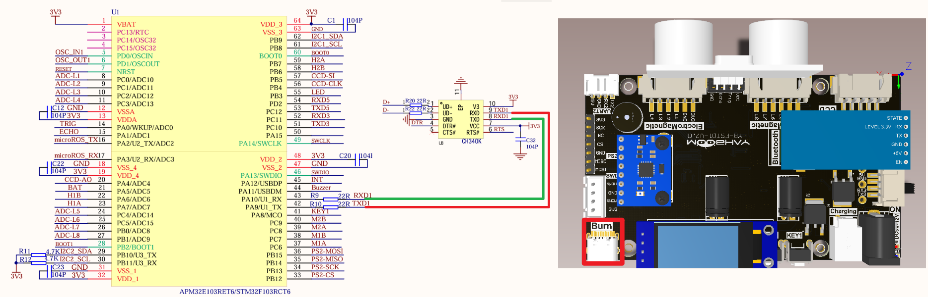
image-20240825210510331

PeripheralsDevelopment boardDescription
USART1_TXPA9USART1 sends data
USART1_RXPA10USART1 receives data

Control principle

xxxxxxxxxx
Serial port related knowledge will not be introduced, mainly DMA knowledge.

STM32F103RCT6 has two DMA controllers, DMA1 has 7 channels and DMA2 has 5 channels;

It is used for high-speed data transmission between peripherals and memory and between memory and memory.

DMA features

DMA initialization and startup are completed by the CPU, and the transfer process is performed by the DMA controller without CPU involvement, thus saving CPU resources for other operations.

DMA1 requests for each channel
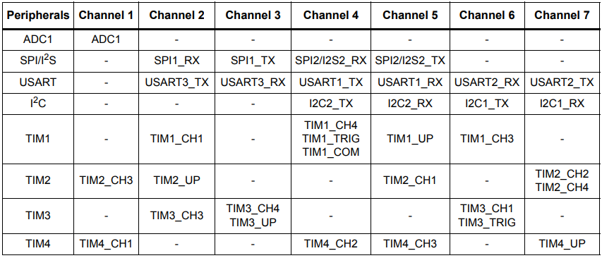
image-20240903164920640

DMA2 requests for each channel

image-20240903164934222

This tutorial uses DMA1 channel 4.

Pin definition

Main control chipPinMain function (after reset)Default multiplexing functionRedefine function
STM32F103RCT6PA9PA9USART1_TX/TIM1_CH2 
STM32F103RCT6PA10PA10USART1_RX/TIM1_CH3 

Software code

Since the default function of the PA9/10 pin is a normal IO pin function, we need to use the multiplexing function.

xxxxxxxxxx
Product supporting data source code path: Attachment → Source code summary → 1.Base_Course → 15.USART+DMA

Control function

The tutorial only briefly introduces the code, and you can open the project source code to read it in detail.

uart_init

​x
void uart_init(u32 bound)
{
    //GPIO port settings
    GPIO_InitTypeDef GPIO_InitStructure;
    USART_InitTypeDef USART_InitStructure;
    NVIC_InitTypeDef NVIC_InitStructure;

    RCC_APB2PeriphClockCmd(RCC_APB2Periph_USART1|RCC_APB2Periph_GPIOA, ENABLE); //Enable USART1, GPIOA clock

    //USART1_TX GPIOA.9
    GPIO_InitStructure.GPIO_Pin = GPIO_Pin_9; //PA.9
    GPIO_InitStructure.GPIO_Speed ••= GPIO_Speed_50MHz;
    GPIO_InitStructure.GPIO_Mode = GPIO_Mode_AF_PP; //Multiplex push-pull output
    GPIO_Init(GPIOA, &GPIO_InitStructure);//Initialize GPIOA.9

    //Initialize USART1_RX GPIOA.10
    GPIO_InitStructure.GPIO_Pin = GPIO_Pin_10;//PA10
    GPIO_InitStructure.GPIO_Mode = GPIO_Mode_IN_FLOATING;//Floating input
    GPIO_Init(GPIOA, &GPIO_InitStructure);//Initialize GPIOA.10
    //USART initialization settings

    USART_InitStructure.USART_BaudRate = bound;//Serial port baud rate
    USART_InitStructure.USART_WordLength = USART_WordLength_8b;//Word length is 8-bit data format
    USART_InitStructure.USART_StopBits = USART_StopBits_1;//One stop bit
    USART_InitStructure.USART_Parity = USART_Parity_No; //No parity bit
    USART_InitStructure.USART_HardwareFlowControl = USART_HardwareFlowControl_None; //No hardware data flow control
    USART_InitStructure.USART_Mode = USART_Mode_Rx | USART_Mode_Tx; //Transmit and receive mode

    USART_Init(USART1, &USART_InitStructure); //Initialize serial port 1
    USART_ITConfig(USART1, USART_IT_RXNE, ENABLE); //Serial port receive interrupt
    USART_Cmd(USART1, ENABLE); //Enable serial port 1

    NVIC_InitStructure.NVIC_IRQChannel = USART1_IRQn;
    NVIC_InitStructure.NVIC_IRQChannelPreemptionPriority = 0;
    NVIC_InitStructure.NVIC_IRQChannelSubPriority = 1; NVIC_InitStructure.NVIC_IRQChannelCmd = ENABLE; 
    NVIC_Init(&NVIC_InitStructure); 
    }

USARTx_DMA_Config

xxxxxxxxxx
void USARTx_DMA_Config(void)
{
    DMA_InitTypeDef DMA_InitStructure;

    // Enable serial port DMA clock
    RCC_AHBPeriphClockCmd(USART_TX_DMA_CLK, ENABLE);
    // Set DMA source address: serial port data register address*/
    DMA_InitStructure.DMA_PeripheralBaseAddr = USART_DR_ADDRESS;
    // Memory address (pointer to the variable to be transferred)
    DMA_InitStructure.DMA_MemoryBaseAddr = (uint32_t)SendBuff;
    // Direction: from memory to peripherals
    DMA_InitStructure.DMA_DIR = DMA_DIR_PeripheralDST;

    // Transfer size
    DMA_InitStructure.DMA_BufferSize = SENDBUFF_SIZE;
    // Peripheral address does not increase
    DMA_InitStructure.DMA_PeripheralInc = DMA_PeripheralInc_Disable;
    // Memory address increment
    DMA_InitStructure.DMA_MemoryInc = DMA_MemoryInc_Enable;
    // Peripheral data unit
    DMA_InitStructure.DMA_PeripheralDataSize =
    DMA_PeripheralDataSize_Byte;
    // Memory data unit
    DMA_InitStructure.DMA_MemoryDataSize = DMA_MemoryDataSize_Byte;

    // DMA mode, one-time or circular mode
    DMA_InitStructure.DMA_Mode = DMA_Mode_Normal;
    //DMA_InitStructure.DMA_Mode = DMA_Mode_Circular;
    // Priority: Medium
    DMA_InitStructure.DMA_Priority = DMA_Priority_Medium;
    // Disable memory-to-memory transfer
    DMA_InitStructure.DMA_M2M = DMA_M2M_Disable;
    // Configure DMA channel
    DMA_Init(USART_TX_DMA_CHANNEL, &DMA_InitStructure);
    // Clear the conversion flag of DMA1 channel 4
    DMA_ClearFlag(USART_TX_DMA_FLAG_TC );
    // Enable DMA
    DMA_Cmd (USART_TX_DMA_CHANNEL,ENABLE);
}

Experimental phenomenon

The USART_DMA.hex file generated by the project compilation is located in the OBJ folder of the [USART+DMA] project. Find the USART_DMA.hex file corresponding to the project and use the FlyMcu software to download the program to the development board.

After the program is successfully downloaded: Use the serial port debugging assistant to view the information, and you can see that the serial port prints Usart1 DMA Class! and Hello (Hello prints for about 300ms).

xxxxxxxxxx
When using the serial port debugging assistant, you need to pay attention to the serial port settings. If the settings are wrong, the phenomenon may be inconsistent
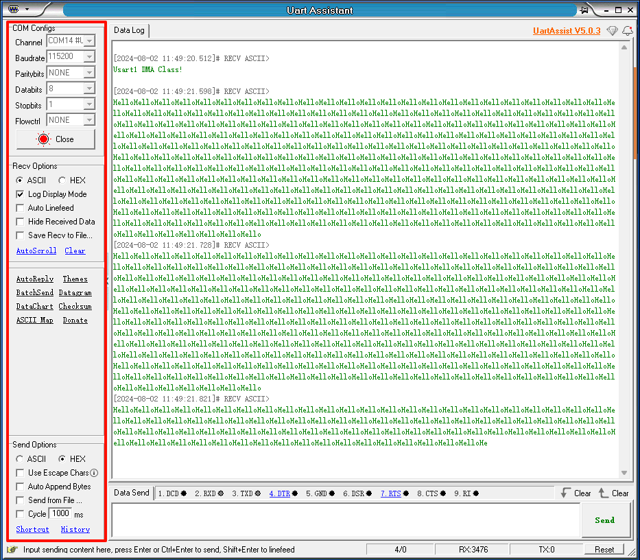
image-20240802114954578

Independent Watchdog (IWDG)
DMA-I2C

COMPANY

  • About us
  • Team Style
  • Blog

LEARNING & EXPLORATION

  • Tutorials
  • Edge AI hardware
  • Educational robots
  • Embedded intelligent hardware

WHERE TO BUY

  • Yahboom Online Store
  • Amazon
  • Alibaba
  • AliExpress
  • Mercado

TECHNOLOGY SUPPORT

  • Email: support@yahboom.com

BE A DISTRIBUTOR

  • Email: sales@yahboom.com
QR Code

Copyright © 2017-2026 Yahboom. All Rights Reserved.

EN/中文