Welcome to MicroROS Self-balancing Robot Car repository
05.MPU6050-Data Read (I2C)
MPU6050: Data Read (I2C)
MPU6050: Data Read (I2C)Hardware connectionControl principlePin definitionSoftware codeControl functionExperimental phenomenon
The tutorial demonstration software simulates I2C communication to read the DMP data of MPU6050, then solves the data and prints it out on the serial port.
The tutorial only introduces the standard library project code
Hardware connection
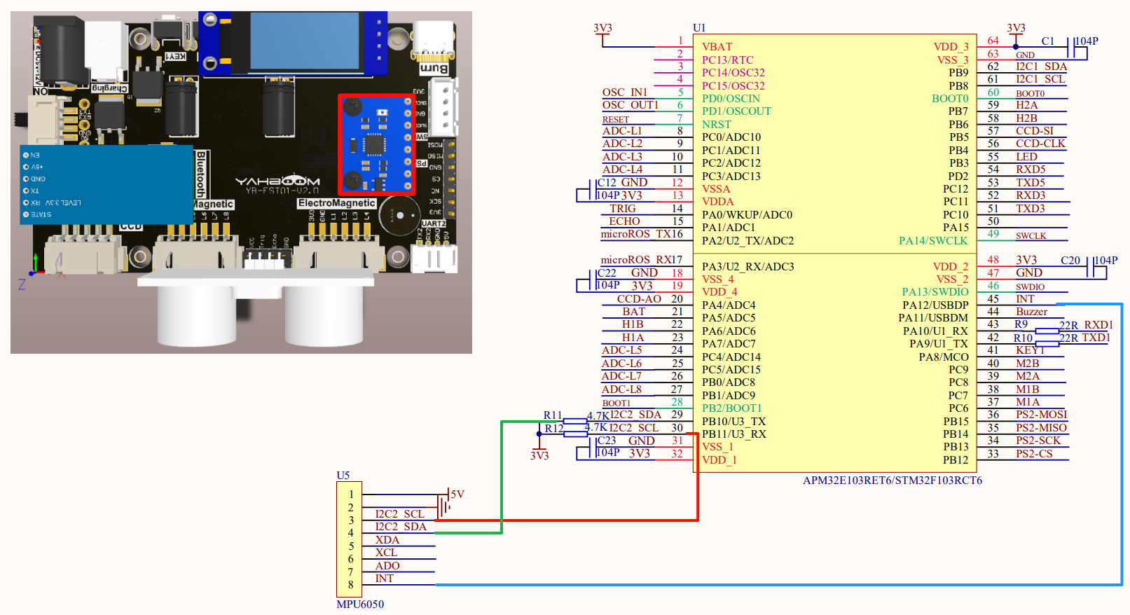
Just install it to the corresponding interface:
| Peripherals | Development Board | Description |
|---|---|---|
| MPU6050: VCC | 5V | OLED power supply |
| MPU6050: GND | GND | OLED common ground |
| MPU6050: SCL | PB10 | Software I2C: Serial clock line (SDA) (pull-up resistor is connected to the module) |
| MPU6050: SDA | PB11 | Software I2C: Serial data line (SCL) (pull-up resistor is connected to the module) |
| MPU6050: XDA | Not connected | I2C master serial data signal line, used for external sensors (pull-up resistors have been connected to the module) |
| MPU6050: XCL | Not connected | I2C master serial clock signal line, used for external sensors (pull-up resistors have been connected to the module) |
| MPU6050: AD0 | Not connected | Slave address setting pin: 1. When grounded or floating, the address is 0x68; 2. When connected to VCC, the address is 0x69 |
| MPU6050: INT | PA12 | Interrupt output pin |
Control principle
The software simulates I2C to obtain DMP data and calculates the pitch, roll, and heading angles.
MPU6050
| Product | MPU6050 |
|---|---|
| Communication method | IIC |
| Transmission rate | 400kHz (Max) |
| Output information | Rotation matrix, quaternion, Euler angle |
| ADC bit number | 16-bit data output |
| Gyroscope range | ±250°, ±500°, ±1000°, ±2000° / s |
| Acceleration range | ±2, ±4, ±8, ±16 G |
| External interface | External magnetometer module |
| Interrupt | INT interrupt trigger pin |
Basic functions
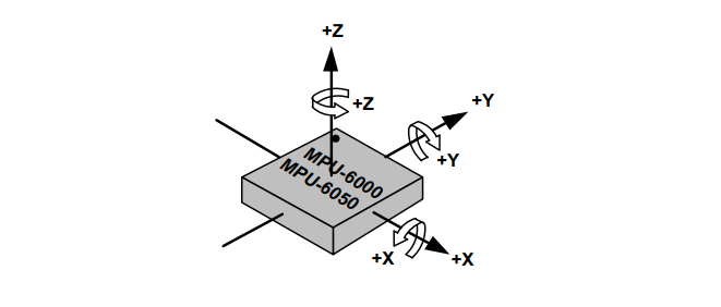
The attitude sensor integrates a three-axis gyroscope, a three-axis accelerometer, and a temperature sensor.
Three-axis gyroscope: can measure the angular velocity around the X, Y, and Z axes, and is used to detect the rotation and turning movement of an object.
xxxxxxxxxxIntegrating the angular velocity can get the angle
Three-axis accelerometer: can measure the acceleration in the X, Y, and Z axis directions, including the acceleration of gravity and the linear acceleration of the object.
Temperature sensor: MPU6050 also integrates a temperature sensor that can measure the temperature of the environment.
Pin definition
| Main control chip | Pin | Main function (after reset) | Default multiplexing function | Redefine function |
|---|---|---|---|---|
| STM32F103RCT6 | PB10 | PB10 | I2C2_SCL/USART3_TX | TIM2_CH3 |
| STM32F103RCT6 | PB11 | PB11 | I2C2_SDA/USART3_RX | TIM2_CH4 |
| STM32F103RCT6 | PA12 | PA12 | USART1_RTS/USBDP/CAN_TX/TIM1_ETR |
Software code
Since the tutorial is software simulation of I2C, the default pin function can be used.
xxxxxxxxxxSource code path for product supporting materials: Attachment → Source code summary → 2. Extended_Course → 5. MPU6050
Control function
The tutorial only briefly introduces the code, and you can open the project source code to read it in detail.
IIC_MPU6050_Init
xxxxxxxxxxvoid IIC_MPU6050_Init(void){GPIO_InitTypeDef GPIO_InitStructure;RCC_APB2PeriphClockCmd(RCC_APB2Periph_GPIOB, ENABLE); //Enable PB port clockGPIO_InitStructure.GPIO_Pin = GPIO_Pin_10|GPIO_Pin_11; //Port configurationGPIO_InitStructure.GPIO_Mode = GPIO_Mode_Out_PP; //Push-pull outputGPIO_InitStructure.GPIO_Speed ••= GPIO_Speed_50MHz; //50MGPIO_Init(GPIOB, &GPIO_InitStructure); //Initialize GPIOB according to the set parameters}
MPU6050_initialize
xxxxxxxxxxvoid MPU6050_initialize(void) {MPU6050_setClockSource(MPU6050_CLOCK_PLL_YGYRO); //Set the clockMPU6050_setFullScaleGyroRange(MPU6050_GYRO_FS_2000); //Gyro range settingMPU6050_setFullScaleAccelRange(MPU6050_ACCEL_FS_2); //Maximum acceleration range +-2GMPU6050_setSleepEnabled(0); //Enter working stateMPU6050_setI2CMasterModeEnabled(0); //Do not let MPU6050 control AUXI2CMPU6050_setI2CBypassEnabled(0); //Master controller I2C and MPU6050 AUXI2C pass-through disabled}
DMP_Init
xxxxxxxxxxvoid DMP_Init(void){u8 temp[1]={0};i2cRead(0x68,0x75,1,temp);printf("mpu_set_sensor complete ......\r\n");if(temp[0]!=0x68)NVIC_SystemReset();if(!mpu_init()){if(!mpu_set_sensors(INV_XYZ_GYRO | INV_XYZ_ACCEL))printf("mpu_set_sensor complete ......\r\n");if(!mpu_configure_fifo(INV_XYZ_GYRO | INV_XYZ_ACCEL))printf("mpu_configure_fifo complete ......\r\n");if(!mpu_set_sample_rate(DEFAULT_MPU_HZ))printf("mpu_set_sample_rate complete ......\r\n");if(!dmp_load_motion_driver_firmware())printf("dmp_load_motion_driver_firmware complete ......\r\n");if(!dmp_set_orientation(inv_orientation_matrix_to_scalar(gyro_orientation)))printf("dmp_set_orientation complete ......\r\n");if(!dmp_enable_feature(DMP_FEATURE_6X_LP_QUAT | DMP_FEATURE_TAP |DMP_FEATURE_ANDROID_ORIENT | DMP_FEATURE_SEND_RAW_ACCEL | DMP_FEATURE_SEND_CAL_GYRO |DMP_FEATURE_GYRO_CAL))printf("dmp_enable_feature complete ......\r\n");if(!dmp_set_fifo_rate(DEFAULT_MPU_HZ))printf("dmp_set_fifo_rate complete ......\r\n");run_self_test();if(!mpu_set_dmp_state(1))printf("mpu_set_dmp_state complete ......\r\n");}}
MPU6050_EXTI_Init
xxxxxxxxxxvoid MPU6050_EXTI_Init(void){GPIO_InitTypeDef GPIO_InitStructure;EXTI_InitTypeDef EXTI_InitStructure;NVIC_InitTypeDef NVIC_InitStructure;RCC_APB2PeriphClockCmd(RCC_APB2Periph_AFIO,ENABLE); //External interrupt, need to enable AFIO clockRCC_APB2PeriphClockCmd(RCC_APB2Periph_GPIOA, ENABLE); //Enable GPIO port clockGPIO_InitStructure.GPIO_Pin = GPIO_Pin_12; //Port configurationGPIO_InitStructure.GPIO_Mode = GPIO_Mode_IPU; //Pull-up inputGPIO_Init(GPIOA, &GPIO_InitStructure); //Initialize GPIO according to the set parametersGPIO_EXTILineConfig(GPIO_PortSourceGPIOA,GPIO_PinSource12);EXTI_InitStructure.EXTI_Line=EXTI_Line12;EXTI_InitStructure.EXTI_Mode = EXTI_Mode_Interrupt;EXTI_InitStructure.EXTI_Trigger = EXTI_Trigger_Falling; //Falling edge triggerEXTI_InitStructure.EXTI_LineCmd = ENABLE;EXTI_Init(&EXTI_InitStructure); //Initialize the peripheral EXTI register according to the parameters specified in EXTI_InitStructNVIC_InitStructure.NVIC_IRQChannel = EXTI15_10_IRQn; //Enable the external interrupt channel where the button is locatedNVIC_InitStructure.NVIC_IRQChannelPreemptionPriority = 0x02; //Preempt priority 2,NVIC_InitStructure.NVIC_IRQChannelSubPriority = 0x01; //Subpriority 3NVIC_InitStructure.NVIC_IRQChannelCmd = ENABLE; //Enable external interrupt channelNVIC_Init(&NVIC_InitStructure);}
Experimental phenomenon
The MPU6050.hex file generated by the project compilation is located in the OBJ folder of the MPU6050 project. Find the MPU6050.hex file corresponding to the project and use the FlyMcu software to download the program to the development board.
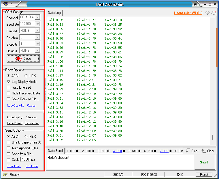
After the program is successfully downloaded: the serial port will receive the data calculated by MPU6050.
xxxxxxxxxxWhen using the serial port debugging assistant, you need to pay attention to the serial port settings. If the settings are wrong, the phenomenon may be inconsistent