yahboom
HomeLearn
Solution
Blog
Online Store
About Us
EN/中文
MicroROS Self-balancing Robot Car📖
01.Introduction
  • 0.Unboxing and Reviewing
  • 1. Must read before use - learning route
  • 2. Introduction to LiDAR
  • 3. Balance car interface description
  • 4. Analysis of common problems
  • 5. Robot charging and battery precautions
02.Assembly tutorial
  • Robot assembly steps
03.Preparation
  • 0.Quick Start (Must Read)
  • 1.Write firmware
  • 2.How to install and use VM
  • 3.ESP32 communication board configuration parameters
  • 4.Connect to microROS agent
04.ROS-WiFi module configuration
  • 0.Serial port configuration WiFi instructions
  • 1.Use ROS-WiFi cam module(must read)
  • 2.Connect to ROS-WiFi cam module agent
  • 3.Camera image correction (optional)
05.Quick start control
  • 1.Keyboard remote control
  • 2.Handle remote control
06.ROS+OpenCV course
  • 1.OpenCV Getting started
  • 2.Geometric transformation
  • 3.Image processing and drawing text line segments
  • 4.Image beautification
07.Mediapipe course
  • 1. Hand detection
  • 2. Posture detection
  • 3. Overall inspection
  • 4. Face detection
  • 5. Face recognition
  • 6. Facial effects
  • 7. 3D object recognition
  • 8. Brush
  • 9. Finger control
  • 10. Gesture recognition
08.Robot basic course
  • 1.Robot information release
  • 2.Robot keyboard control
  • 3.Robot handle control
  • 4.Robot state estimation
  • 5.Line speed calibration
  • 6.Angular velocity calibration
  • 7.Robot URDF model
09.Lidar course
  • 1.Lidar avoid
  • 2.Lidar following
  • 3.Lidar guard
  • 5.Gmapping mapping
  • 6.Cartographer mapping
  • 7.Navigation2 navigation avoid
  • 8.Navigation2 fast relocation navigation
  • 9.ROS Robot APP mapping
  • 10.ROS Robot APP navigation
10.Robot visual interaction
  • 1.Color tracking
  • 2.Object recognition and tracking
  • 3.Face recognition tracking
  • 4.Autonomous driving line patrol
  • 5.QR code motion control
  • 6.Gesture control car movement
  • 7.Palm control car movement
  • 8.Gesture control car action group
  • 9.Palm recognition and tracking
  • 10.Human body posture recognition and tracking
11.Multi-machine course
  • 1.Multi-machine handle control
  • 2.Multi-machine keyboard control
  • 3.Multi-machine navigation
  • 4.Multi-machine rapid relocation navigation
12.STM32 balancing case
01.Environment construction and development
  • 13.Window Watchdog (WWDG)
  • 01.MDK-ARM installation
  • 02.STM32CubeIDE installation
  • 03.Common driver installation
  • 04.Download the program
  • 05.MDK-ARM project usage
  • 06.Program simulation
02.STM32 getting started course
  • 01.Project creation
  • 02.LED Control(GPIO)
  • 03.Buzzer control(GPIO)
  • 04.Button control(EXTI)
  • 05.Serial communication(USART)
  • 06.Voltage detection(ADC)
  • 07.Basic timer(TIM)
  • 08.Universal timer(TIM)
  • 09.Advanced Timer(TIM)
  • 10.I2C Communication(I2C)-OLED
  • 11.SPI communication(SPI)-2.4G handle
  • 12.Independent Watchdog (IWDG)
  • 14.DMA-USART
  • 15.DMA-I2C
03.STM32 expansion course
  • 01.Battery voltage detection (ADC)
  • 02.Ultrasonic module-measuring distance (TIM)
  • 03.Motor drive+encoder (TIM)
  • 04.OLED Data-Display(I2C)
  • 05.MPU6050-Data Read (I2C)
04.Robot car PID control course
  • 01.PID basic concept
  • 02.PID example analysis
  • 03.P, PI, PD controller theory
  • 04.Position PID
  • 05.Incremental PID
  • 06.Cascade PID
  • 07.Balance principle of car
  • 08.Car upright control (PD)
  • 09.Car speed ​​control (PI)
  • 10.Car steering control (PD)
  • 11.Got angle and angular velocity (DMP algorithm)
  • 12.Got angle and angular velocity (Kalman filter algorithm)
  • 13.Got angle and angular velocity(Complementary filter algorithm)
05.Robot car basic course
  • 01.Car parameter adjustment
  • 02.Ultrasonic obstacle avoidance
  • 03.Ultrasonic follow
  • 04.Bluetooth remote control
  • 05.Load balance
  • 06.Radar obstacle avoidance
  • 07.Radar guard
  • 08.Radar follow
  • 09.Radar patrol
  • 10.Radar wall following go in a straight line
  • 11.Radar tracking wall multiple walls
06.Robot car LQR control
  • Balance car LQR high-level control
07.Circuit design
  • 01.Overall circuit design
  • 02.STM32 minimum system
  • 03.Serial port circuit design
  • 04.Power circuit design
  • 05.MPU6050 Circuit Design
  • 06.Motor drive circuit design
08.Mathematical model
  • Balance car mathematical model
13.Linux basic course
  • 1.Introduction to Linux system
  • 2.Ubuntu file system
  • 3.Ubuntu common commands
  • 4.Ubuntu common editors
  • 5.Ubuntu software operation commands
  • 6.Virtual machine installation
  • 7.SSH remote control
  • 8.VNC remote control
  • 9.Transfer files remotely
  • 10.Driver library and communication
  • 11.Static IP and hotspot mode
  • 12.Bind device ID
  • 13.Capacity expansion and resource allocation
  • 14.Update system software sources
  • 15.Set root user password
  • 16.sudo free password
  • 17.Connect to WiFi network
  • 18.View system version
  • 19.Customized service management
  • 20.Back up system image
14.Docker course
  • 1. Overview and installation
  • 2. Common commands
  • 3. Docker images deeply understand and publish images
  • 4. Docker hardware interaction and data processing
  • 5. Enter the bot's docker container
15.ROS2 basic course
  • 1.Introduction to ROS2
  • 2.ROS2 install Humble
  • 3.ROS2 development environment
  • 4.ROS2 workspace
  • 5.ROS2 function package
  • 6.ROS2 node
  • 7.ROS2 topic communication
  • 8.ROS2 service communication
  • 9.ROS2 action communication
  • 10.ROS2 custom interface message
  • 11.ROS2 parameter service case
  • 12.ROS2 meta-function package
  • 13.ROS2 distributed communication
  • 14.ROS2 DDS
  • 15.ROS2 time related API
  • 16.ROS2 common command tools
  • 17.ROS2 rviz2 use
  • 18.ROS2 rqt toolbox
  • 19.ROS2 Launch startup file configuration
  • 20.ROS2 recording and playback tool
  • 21.ROS2 URDF model
  • 22.ROS2 Gazebo simulation platform
  • 23.ROS2 TF2 coordinate transformation
Download
  • RemoteCtrl_APP(Android)
  • Mapping_APP(iOS_Android)
  • Code
  • Hardware Information
  • software tools
  • 3D model file
  • Instruction manual
  • VM image file
  • ROS2_Basic_VM
Download ZIP

Welcome to MicroROS Self-balancing Robot Car repository

11.Radar tracking wall multiple walls

Radar wall tracking: multiple walls

Radar wall tracking: multiple wallsHardware connectionControl PrincipleMain codeProgram flow chartExperimental phenomenon

The tutorial mainly demonstrates the wall patrol function of the balance car combined with the Tmini-Plus radar (maintaining a certain distance from the nearest wall).

xxxxxxxxxx
The tutorial only introduces the standard library project code

Hardware connection

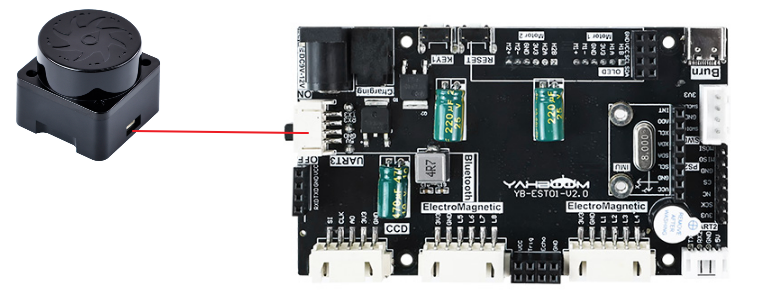
Since we have configured a special connection line, we only need to install it to the corresponding interface.

PeripheralsDevelopment Board
Tmini-Plus Radar: VCC5V
Tmini-Plus Radar: TXDPC10
Tmini-Plus Radar: RXDPC11
Tmini-Plus Radar: GNDGND

image-20250109185937991

Control Principle

The radar data is parsed by the program, and the distance from the wall and the distance to be maintained for patrolling the wall are set according to the distance collected by the program initialization (radar 72° distance). The 0° distance determines whether there is an obstacle in front.

xxxxxxxxxx
The right side of the radar needs to be close to the wall, and the angle of distance measurement is 72°
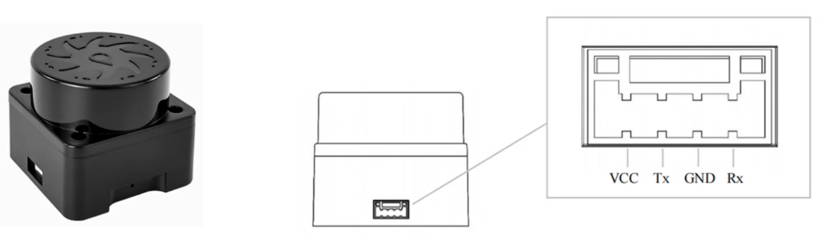
  • Tmini-Plus radar

image-20240820102356793

Product nameTmini-Plus radar
Scanning frequency6-12Hz
Sampling frequency4000 times/s
Measuring radiusBlack object: 12m
Minimum measuring distance0.05m
Distance measurement principleTOF distance measurement
Scanning angle360°
Communication interfaceStandard asynchronous serial port (UART)
1. Baud rate: 230400
2. Data bits: 8
3. Check bit: None
4. Stop bit: 1
ROS supportROS1/ROS2
Windows supportHost computer

Radar angle distribution

The arrow in the center of the radar points to 0°/360°, and the angle increases clockwise.
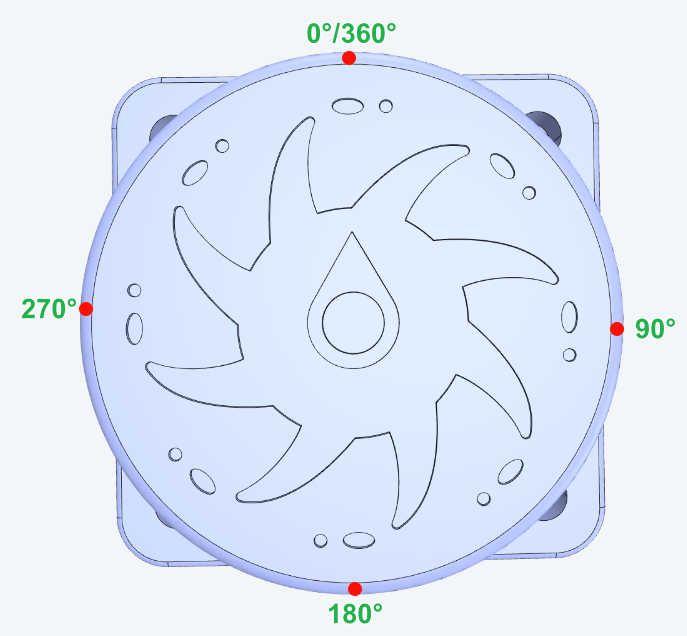
image-20240820204047537

Communication protocol

xxxxxxxxxx
For detailed information, please refer to the "T_Mini_Plus Manual"

Main code

The tutorial mainly explains the code for the radar wall-following function. For detailed code, please refer to the corresponding project file.

LiDar_Straight

The radar wall patrol function adds a turning action to the radar wall patrol function. When there is no obstacle in front of the radar, the radar maintains the wall patrol function. When an obstacle is detected in front of the radar, the radar turns left.

void LiDar_Straight(void) 
{
    static u16 target_distance=0;
    
    u16 current_distance=target_distance;
    
    static u16 Limit_distance=0;   //Maximum detection range of radar
    static u16 get_timedis = 0; 
    
    for (u8 i = 0;i<5;i++) //The detection distance is 72 degrees
    {
        if(get_timedis<GET_LidarDIS_Time)
        {
            if(Tminidis[Lidar_Angle]==0 || Tminidis[Lidar_Angle]>400) continue; //Discard data with values of 0 and greater than 400mm
            
            get_timedis ++;
            target_distance = Tminidis[Lidar_Angle];//Dynamically obtain the target angle
            Limit_distance=target_distance+200;//200mm greater than the target distance, mainly to avoid the disappearance of the reference object causing the car to quickly turn
            
            if(get_timedis == (GET_LidarDIS_Time-1)) 
            {
                g_lidar_go_flag = 1;
                get_timedis = GET_LidarDIS_Time;
            }
        }
        
         if(Tminidis[Lidar_Angle]<(Limit_distance))//Limit the detection range of the radar
        {
             current_distance=Tminidis[Lidar_Angle];//Determine distance
        }
                
    }
    
    if(get_timedis<GET_LidarDIS_Time) //Do not take any action until the distance is determined
    {
        return;
    }
    
    
    if(Tminidis[0]>0 && Tminidis[0]<Limit_distance)//Determine the obstacle avoidance distance based on the initial value; Because the following distance is 72 degrees, only a left turn is needed
    {
        if(lidar_wall_flag == 0)
        {
            lidar_wall_flag = 1;
            myTurn_Kd = 30;
            Move_Z = -600; //turnleft
            delay_time_int(1);//10ms 
        }
            Move_X = 0; 
            Last_error = 0;//Clear PID errors to avoid excessive steering
            return;
    }
    
    if(get_time_int()!=0)
    {
        return;
    }
    else 
    {
        if(lidar_wall_flag ==1)
        {
            lidar_wall_flag = 0;
            Move_X = 0;
            Move_Z = 0;
            myTurn_Kd = 0;
            return;
        } 
        
    }
    
    Set_track_speed();
    
    Move_Z = Distance_Adjust_PID(current_distance,target_distance);
}

Distance_Adjust_PID

Perform PID processing based on the distance between the radar and the wall. If the balancing car does not patrol the wall in a straight line effectively, modify the PID parameters of the app_lidar_car.c file. It is not recommended to modify the PID parameters of the pid_control.c file (the PID parameters of the pid_control.c file shall be based on the parameters finally confirmed in the balancing car parameter adjustment tutorial).

float Distance_Adjust_PID(float Current_Distance,float Target_Distance)//PID PID Distance adjustment PID
{

    error=Target_Distance-Current_Distance;                             //Calculate deviation
    OutPut=-Track_Lidar_KP*error-Track_Lidar_KD*(error-Last_error);                             //Position based PID controller
    Last_error=error;                                                           //Save last deviation
    return OutPut;                                              
}

Program flow chart

Briefly introduce the process of function implementation:
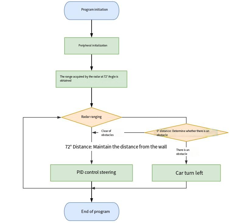
image-20240904174442613

xxxxxxxxxx
The 72° (right side) of the radar is to detect and maintain the distance from the wall. If you encounter an obstacle in front, you only need to turn left

Experimental phenomenon

Software code

The Balance_Radar_wall_line.hex file generated by the project compilation is located in the OBJ folder of the Balance_Radar_wall_line project. Find the Balance_Radar_wall_line.hex file corresponding to the project and use the FlyMcu software to download the program into the development board.

xxxxxxxxxx
Product supporting materials source code path: Attachment → Source code summary → 5.Balanced_Car_Extended → 17.Balance_Radar_wall_line

Experimental phenomenon

After the program is started, press KEY1 according to the OLED prompt to start the radar wall-following function of the balance car:

OLED displays wait get dis!: The balance car will take 1 second to obtain the distance of the wall that the radar needs to patrol (the right side of the radar needs to be close to the wall, and the source of the wall patrol distance is the 72° position of the radar); OLED displays start track!: Start the radar wall-following mode.

If an obstacle is encountered during the patrol process, it will turn left; after turning left, it will resume the wall-following mode.

xxxxxxxxxx
The program has voltage detection. If the voltage is less than 9.6V, a low voltage alarm is triggered and the buzzer will sound.
Common situations for triggering voltage alarms:
1. The power switch of the development board is not turned on, and only the Type-C data cable is connected for power supply
2. The battery pack voltage is lower than 9.6V and needs to be charged in time
Radar wall following go in a straight line
Balance car LQR high-level control

COMPANY

  • About us
  • Team Style
  • Blog

LEARNING & EXPLORATION

  • Tutorials
  • Edge AI hardware
  • Educational robots
  • Embedded intelligent hardware

WHERE TO BUY

  • Yahboom Online Store
  • Amazon
  • Alibaba
  • AliExpress
  • Mercado

TECHNOLOGY SUPPORT

  • Email: support@yahboom.com

BE A DISTRIBUTOR

  • Email: sales@yahboom.com
QR Code
QR Code

Copyright © 2017-2026 Yahboom. All Rights Reserved.

EN/中文