Welcome to Wheeled Chassis Kit repository
For RPi5
Drive motor and read encoder-USART
1.1 Explanation
Please read 《0. Motor introduction and usage》first to understand the motor parameters, wiring method, and power supply voltage you are currently using. To avoid improper operation and damage to the driver board or motor.
I2C and serial communication cannot be shared, only one can be selected.
Hardware wiring:
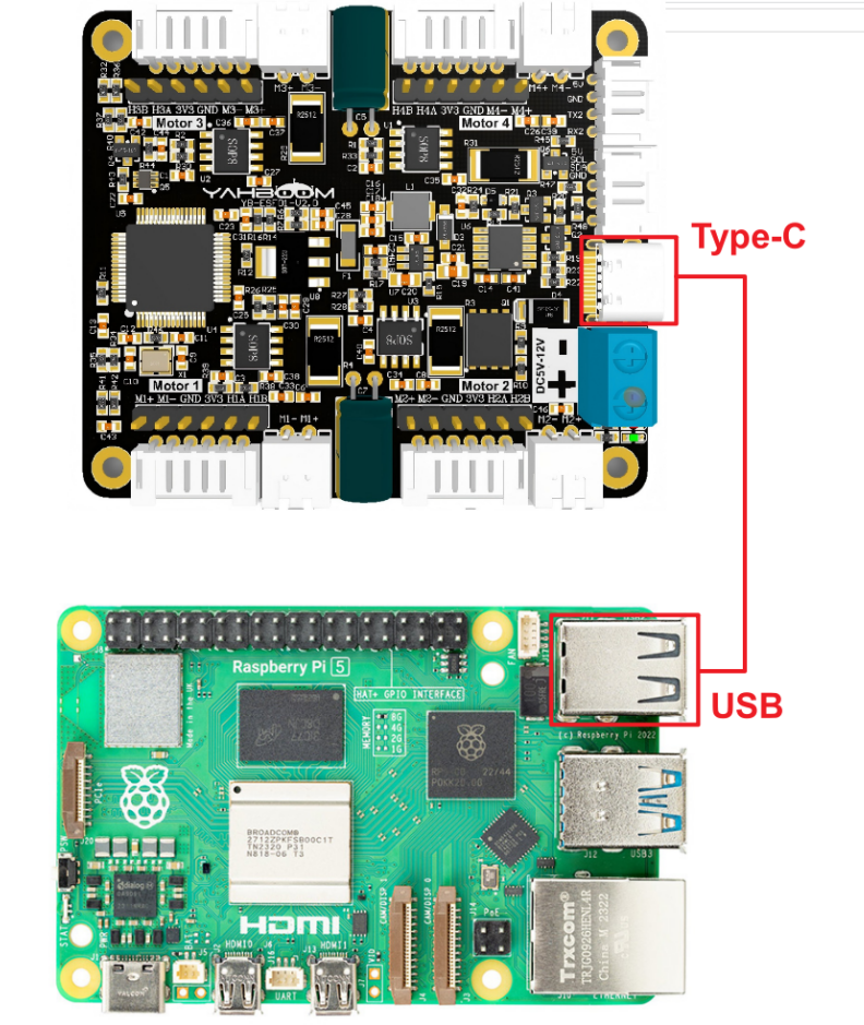
When Raspberry Pi 5 board and driver board use serial port communication, just connect the USB port on the mainboard to the TYPE-C port on the 4-channel motor driver board.
| Motor | 4-channel motor driver board(Motor) |
|---|---|
| M2 | M- |
| V | 3V3 |
| A | H1A |
| B | H1B |
| G | GND |
| M1 | M+ |
1.2 Instructions
After the Raspberry Pi 5 board is connected to the USB of the driver board, you can use the following command to check whether the serial port is recognized.
ls /dev/ttyUSB*
In normally, /dev/ttyUSB0 will be displayed. If there is no ttyUSB0 but ttyUSB1, you need to change port='/dev/ttyUSB0' at the beginning of the code to port='/dev/ttyUSB1'
Then, use file transfer software, such as WinSCP, which needs to be searched and downloaded by yourself.
Transfer the py file to the root directory of the RDK board through the software, then open the terminal and run the command.
xxxxxxxxxxsudo python ~/USART.py
1.3 Code analysis
xUPLOAD_DATA = 3 #0:不接受数据 1:接收总的编码器数据 2:接收实时的编码器 3:接收电机当前速度 mm/s #0: Do not receive data 1: Receive total encoder data 2: Receive real-time encoder 3: Receive current motor speed mm/s
MOTOR_TYPE = 1 #1:520电机 2:310电机 3:测速码盘TT电机 4:TT直流减速电机 5:L型520电机 #1:520 motor 2:310 motor 3:speed code disc TT motor 4:TT DC reduction motor 5:L type 520 motorUPLOAD_DATA: used to set the data of the motor encoder. Set 1 to the total number of encoder pulses and 2 to the real-time pulse data of 10ms.
MOTOR_TYPE: used to set the type of motor used. Just modify the corresponding numbers according to the comments according to the motor you are currently using. You don’t need to modify the rest of the code.
If you need to drive the motor and observe the data, just modify the two numbers at the beginning of the program. No changes are required to the rest of the code.
xxxxxxxxxxdef set_motor_parameter():
    if MOTOR_TYPE == 1:        set_motor_type(1)  # 配置电机类型        time.sleep(0.1)        set_pluse_phase(30)  # 配置减速比,查电机手册得出        time.sleep(0.1)        set_pluse_line(11)  # 配置磁环线,查电机手册得出        time.sleep(0.1)        set_wheel_dis(67.00)  # 配置轮子直径,测量得出        time.sleep(0.1)        set_motor_deadzone(1900)  # 配置电机死区,实验得出        time.sleep(0.1)
    elif MOTOR_TYPE == 2:        set_motor_type(2)        time.sleep(0.1)        set_pluse_phase(20)        time.sleep(0.1)        set_pluse_line(13)        time.sleep(0.1)        set_wheel_dis(48.00)        time.sleep(0.1)        set_motor_deadzone(1600)        time.sleep(0.1)
    elif MOTOR_TYPE == 3:        set_motor_type(3)        time.sleep(0.1)        set_pluse_phase(45)        time.sleep(0.1)        set_pluse_line(13)        time.sleep(0.1)        set_wheel_dis(68.00)        time.sleep(0.1)        set_motor_deadzone(1250)        time.sleep(0.1)
    elif MOTOR_TYPE == 4:        set_motor_type(4)        time.sleep(0.1)        set_pluse_phase(48)        time.sleep(0.1)        set_motor_deadzone(1000)        time.sleep(0.1)
    elif MOTOR_TYPE == 5:        set_motor_type(1)        time.sleep(0.1)        set_pluse_phase(40)        time.sleep(0.1)        set_pluse_line(11)        time.sleep(0.1)        set_wheel_dis(67.00)        time.sleep(0.1)        set_motor_deadzone(1900)        time.sleep(0.1)
This is used to store the parameters of the Yahboom motor. By modifying the MOTOR_TYPE parameter above, one-click configuration can be achieved.
In normally, do not modify the code here when using the Yahboom motor.
If you are using your own motor, or if a certain data needs to be modified according to your needs, you can check the course《1.2 Control command》 to understand the specific meaning of each command.
xxxxxxxxxxif __name__ == "__main__":    try:        t = 0        print("please wait...")        send_upload_command(UPLOAD_DATA)#给电机模块发送需要上报的数据 Send the data that needs to be reported to the motor module        time.sleep(0.1)        set_motor_parameter()#设计电机参数  Design motor parameters
        while True:            received_message = receive_data()  # 接收消息    Receiving Messages            if received_message:    # 如果有数据返回 If there is data returned                parsed = parse_data(received_message) # 解析数据 Parsing the data                if parsed:                    print(parsed)  # 打印解析后的数据   Print the parsed data
            t += 10            M1 = t            M2 = t            M3 = t            M4 = t
            if MOTOR_TYPE == 4:                control_pwm(M1*2, M2*2, M3*2, M4*2)            else:                control_speed(M1, M2, M3, M4)#直接发送命令控制电机  Send commands directly to control the motor
            if t> 1000 or t < -1000:                t = 0
            time.sleep(0.1)
In the loop program, the speed of the four motors will be slowly increased from 0 to 1000. If the motor type is 4, that is, the motor without encoder, the motor's PWM is directly controlled.
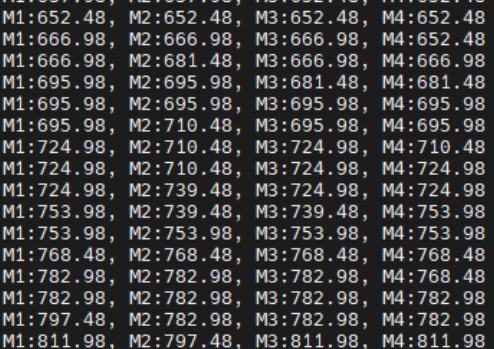
At the same time, the data sent by the driver board is read and printed out at the same time.
xxxxxxxxxxdef parse_data(data):    data = data.strip()  # 去掉两端的空格或换行符   Remove spaces or line breaks at both ends
    if data.startswith("$MAll:"):        values_str = data[6:-1]  # 去除 "$MAll:" 和 "#" Remove "$MAll:" and "#"        values = list(map(int, values_str.split(',')))  # 分割并转换为整数  Split and convert to integer        parsed = ', '.join([f"M{i+1}:{value}" for i, value in enumerate(values)])        return parsed    elif data.startswith("$MTEP:"):        values_str = data[6:-1]        values = list(map(int, values_str.split(',')))        parsed = ', '.join([f"M{i+1}:{value}" for i, value in enumerate(values)])        return parsed    elif data.startswith("$MSPD:"):        values_str = data[6:-1]        values = [float(value) if '.' in value else int(value) for value in values_str.split(',')]        parsed = ', '.join([f"M{i+1}:{value}" for i, value in enumerate(values)])        return parsed
The saved original data is extracted and reconstructed into a new printing format.
1.4 Experimental phenomenon
After connecting the type-c port on the driver board to the USB port on the motherboard, place the program in the root directory and run the command sudo python ~/USART.py. You can see that the motor will gradually speed up, then stop, and repeat.
At the same time, you can see the printed motor value in the terminal constantly changing.