Welcome to Wheeled Chassis Kit repository
7. PWM breathing light
PWM breathing light
PWM breathing light1. Learning objectivesPWM principleBasic PWM Parameters2. Hardware Construction3. Experimental steps1. Open the SYSCONFIG configuration tool2. PWM parameter configuration3. Write the program4. Compile4. Program Analysis5. Experimental phenomenon
1. Learning objectives
- Learn the principle of PWM breathing light.
- Output a PWM signal through TIMG6_C0 to control the LED indicator from dark to bright, and then from bright to dark, similar to human breathing.
PWM principle
PWM is the abbreviation of Pulse Width Modulation, which means pulse width modulation in Chinese. It is a very effective technology that uses the digital output of the microprocessor to control the analog circuit. Its advantages such as simple control, flexibility and good dynamic response make it the most widely used control method in power electronics technology. Its application fields include measurement, communication, power control and conversion, motor control, servo control, dimming, switching power supply, and even some audio amplifiers. Therefore, learning PWM has very important practical significance.
In fact, we can also understand it this way. PWM is a method of digitally encoding the level of analog signals. Through the use of high-resolution counters, the duty cycle of the square wave is modulated to encode the level of a specific analog signal. PWM signals are still digital because at any given moment, the full-scale DC power supply is either fully present (ON) or completely absent (OFF). The voltage or current source is applied to the analog load in a repetitive sequence of pulses that are either on (ON) or off (OFF). On is when the DC power supply is applied to the load, and off is when the power supply is disconnected. As long as the bandwidth is sufficient, any analog value can be encoded using PWM.
Basic PWM Parameters
PWM is pulse width modulation, which has two very important parameters: frequency and duty cycle.
- Frequency: The frequency of PWM is the inverse of the entire cycle, that is, the number of times the PWM signal is repeated per unit time. It indicates how many signal cycles are completed per second. The frequency determines the rate at which the PWM signal changes. The higher the frequency, the shorter the signal cycle and the more times it changes.
- Duty Cycle: The duty cycle refers to the proportion of the high level in a cycle. It is usually expressed as a percentage. It reflects the "width" of the PWM signal, that is, the ratio of the duration of the high level part to the total cycle time. The duty cycle determines the average output voltage of the signal. The larger the duty cycle, the higher the average output voltage.
2. Hardware Construction
We introduced earlier that the MSPM0G series has a total of 7 timers, which can be divided into 2 types, general timer (TIMG) and advanced control timer (TIMA). The PWM function is implemented on the basis of the timer. From the user manual, we can know that MSPM0G3507 has 7 timers. Which timer has PWM function needs to refer to the pin description of the data manual. Each PWM channel corresponds to a pin of the microcontroller. This pin is not unique and fixed. One or two pins may correspond to the same channel. For example, TIMG_C0 corresponds to PA5 and PA12, which means that both PA5 and PA12 pins can be configured as channel 0 of the timer. When using it, we can choose any one of them for configuration.


This case uses the PB2 pin of LED1, configured as channel 0 of timer 6, to generate a PWM signal to control the on and off of the light.

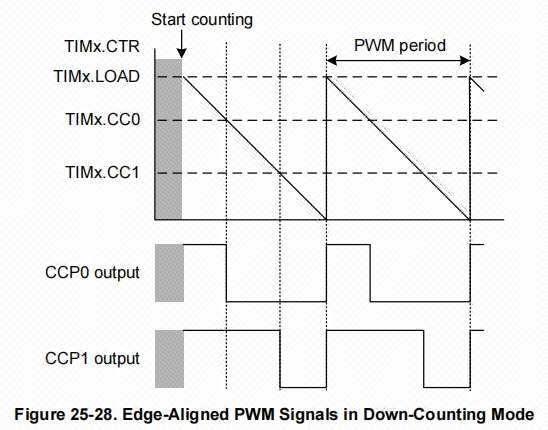
There are two modes of PWM. One is edge-aligned PWM, which refers to the down-counting mode used by the timer. The output channel will output a high level when the timer starts counting. When the count value is the same as the comparison value of the output channel (CC0 and CCP0, CC1 and CCP1 in the figure), the output channel will output a low level until the count value of the timer counts to 0, completing a cycle of pulse output.
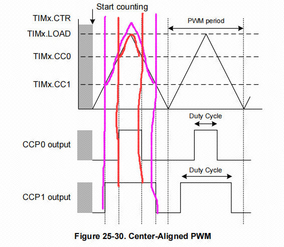
The other mode is center-aligned mode, which refers to the up-down counting mode of the timer. The output channel will output a low level at the start of the timer, and flip the level once when the timer counts up and counts down twice to reach the comparison value of the output channel.
3. Experimental steps
By driving the PWM signal to achieve the breathing light effect, by changing the duty cycle of the PWM signal, the current flowing through the LED can be adjusted, thereby achieving a gradual change in the brightness of the LED. Generally speaking, the human eye does not have a noticeable flickering sensation for refresh frequencies above 80Hz, because flickering cannot be detected at higher frequencies. The larger the duty cycle, the brighter the LED; the smaller the duty cycle, the dimmer the LED. Therefore, when the frequency is fixed, the brightness of the LED can be controlled by adjusting the duty cycle, thereby achieving a breathing light effect. In this case, the onboard LED light (PB2) will be used to achieve the breathing light effect, which gradually lights up and then gradually turns off.
1. Open the SYSCONFIG configuration tool
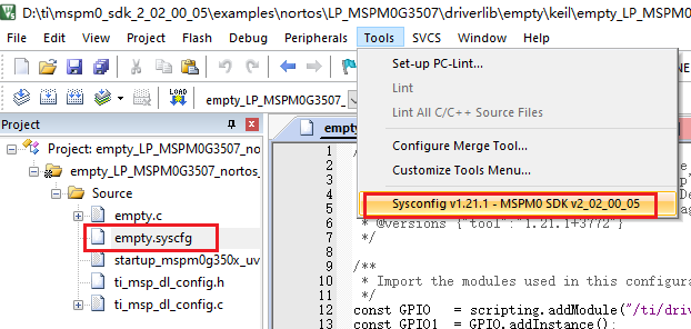
Open the blank project empty in the SDK in KEIL.
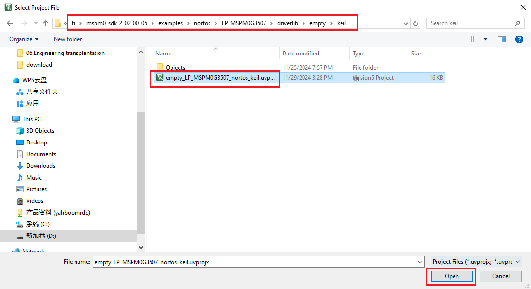
Open after selecting, open the empty.syscfg file in the keil interface, when the empty.syscfg file is open, then select to open the SYSCONFIG GUI interface in the Tools column.
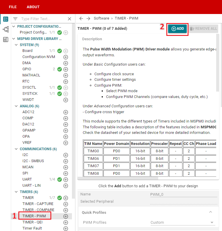
In SYSCONFIG, select MCU peripherals on the left, find the TIMER-PWM option and click to enter. Click ADD in TIMER-PWM to add the PWM peripheral under the timer.
2. PWM parameter configuration
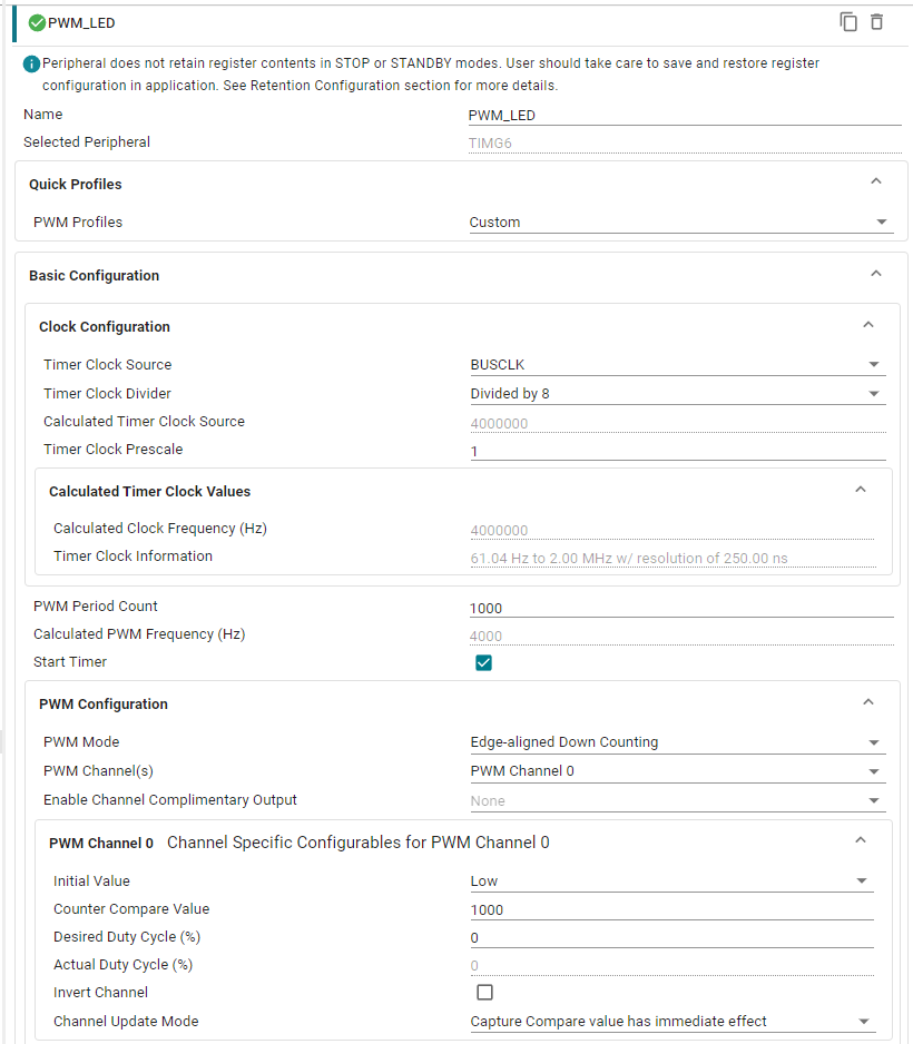
Here, set channel 0 to 4kHz frequency, 0% duty cycle PWM, cycle count value to 1000, and compare value to 1000. In this way, count down from 1000, and the PWM state will flip every time 1000 is encountered.
Parameter description:
Name: custom name. Here it is set to PWM_LED
PWM Profiles: configure PWM template, select the default one.
Timer Clock Source: the clock source of the timer, select BUSCLK (bus clock), the default frequency is 32MHz.
Timer Clock Divider: Set the timer clock divider to 8 division.
Calculated Timer Clock Source: Displays the clock frequency after division.
Timer Clock Prescale: Timer pre-allocation. We configure TIMG6, a 16-bit timer, which supports pre-division. No pre-division is set here.
Calculated Clock Freguency (Hz): Displays the frequency after division and pre-division.
PWM Period Count: PWM period count value. Here we set it to 1000.
Calculated PwM Frequency(Hz): The software automatically calculates the PWM frequency, which is displayed as 4000.
Start Timer: Whether to start the timer. Check it here to start the timer PWM output on power-on.
PWM Mode: PWM mode. Configured as Edge-aligned Down Counting edge alignment mode and down counting mode.
PWM Channel(s): PWM channel. Configured to only turn on channel 0.
Enable Channel Complimentary Output: Whether to enable channel complementary output. Not enabled here.
Initial Value: The default output state of the PWM channel. Configured as the default low-level output.
Counter Compare Value: The comparison value of PWM. Configured as 1000, that is, the setting range of the PWM duty cycle is 0-999.
Desired Duty cycle (%): The duty cycle of PWM. The default duty cycle of 0 is used here.
Actual Duty cycle (%): Displays the actual duty cycle automatically calculated by the software.
Invert Channel: Whether to enable invert output. Not enabled here.
Channel Update Mode: Channel update mode. Configured as Capture Compare value has immediate effect, the comparison value is updated immediately.

LED1's control pin is PB2, and PB2 has a timer 6 channel 0, so select TIMG6, PB2/50 here.
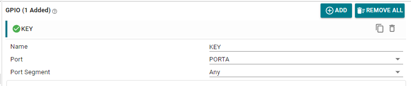
We have already occupied the PB2 pin of LED1 with PWM, and it can no longer be used for GPIO peripherals, so it needs to be removed. Currently, there is only one button configuration left in the GPIO peripheral in the example.
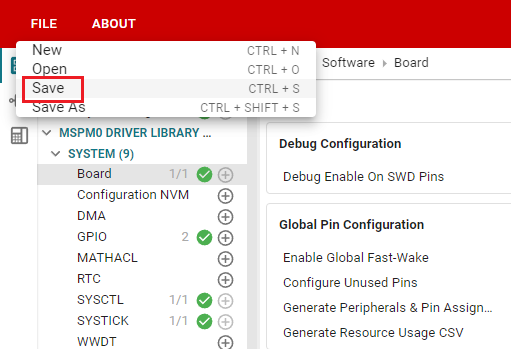
Click SAVE to save the configuration in SYSCONFIG, then turn off SYSCONFIG and return to keil.
Select Yes to All in the pop-up window
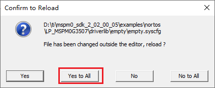
Similarly, we also need to confirm whether the ti_msp_dl_config.c and ti_msp_dl_config.h files are updated. Compile directly, and the compilation will automatically update to keil. If there is no update, we can also copy the file content in SYSCONFIG.
3. Write the program
In the empty.c file, write the following code
x#include "ti_msp_dl_config.h"volatile unsigned int delay_times = 0;//搭配滴答定时器的精准毫秒级延时 Precise millisecond delay with tick timervoid delay_ms(unsigned int ms){ delay_times = ms; while( delay_times != 0 );}int main(void){ int i = 0; SYSCFG_DL_init(); while (1) { // 呼吸灯渐亮过程 Breathing light gradually brightens for (i = 0; i <= 999; i++) { // 设置 LED 亮度 Setting LED Brightness DL_TimerG_setCaptureCompareValue(PWM_LED_INST,i,GPIO_PWM_LED_C0_IDX); delay_ms(1); // 延迟以控制亮度变化速度 Delay to control the speed of brightness change } // 呼吸灯渐暗过程 Breathing light dimming process for (i = 999; i > 0; i--) { // 设置 LED 亮度 Setting LED Brightness DL_TimerG_setCaptureCompareValue(PWM_LED_INST,i,GPIO_PWM_LED_C0_IDX); delay_ms(1); // 延迟以控制亮度变化速度 Delay to control the speed of brightness change } }}//滴答定时器的中断服务函数 Tick ??timer interrupt service functionvoid SysTick_Handler(void){ if( delay_times != 0 ) { delay_times--; }}4. Compile
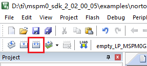
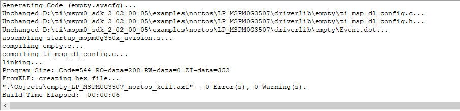
Click the Rebuild icon. The following prompt appears, indicating that the compilation is complete and there are no errors.
4. Program Analysis
- empty.c
xxxxxxxxxxint main(void){ int i = 0; SYSCFG_DL_init(); while (1) { // 呼吸灯渐亮过程 Breathing light gradually brightens for (i = 0; i <= 999; i++) { // 设置 LED 亮度 Setting LED Brightness DL_TimerG_setCaptureCompareValue(PWM_LED_INST,i,GPIO_PWM_LED_C0_IDX); delay_ms(1); // 延迟以控制亮度变化速度 Delay to control the speed of brightness change } // 呼吸灯渐暗过程 Breathing light dimming process for (i = 999; i > 0; i--) { // 设置 LED 亮度 Setting LED Brightness DL_TimerG_setCaptureCompareValue(PWM_LED_INST,i,GPIO_PWM_LED_C0_IDX); delay_ms(1); // 延迟以控制亮度变化速度 Delay to control the speed of brightness change } }}After initializing the hardware, enter the breathing light loop. Use the duty cycle of the PWM signal to control the brightness of the LED light. The breathing light gradually brightens and gradually dims uses two for loops to gradually adjust the PWM duty cycle from 0 to 999 and then from 999 to 0. delay_ms(1) sets the brightness change interval to 1 millisecond. The breathing light change speed can be controlled by adjusting the parameters of the delay function.
5. Experimental phenomenon
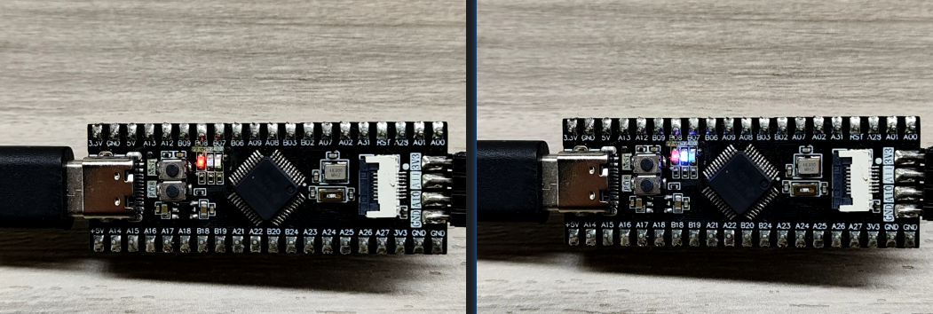
After the program is downloaded, you can see that the LED light gradually turns on and off, showing a breathing light effect.