yahboom
HomeLearn
Solution
Blog
Online Store
About Us
EN/中文
Wheeled Chassis Kit📖
0.Chassis installation course
  • Installation Video-1
  • Installation Video-2
  • Installation Video-3
1.4-channel motor drive module tutorials
Motor introduction and commissioning
  • 1. Motor introduction and usage
  • 2.PC host
IIC communication
  • For Arduino
  • For ESP32
  • For JetsonNANO
  • For MSPM0
  • For PICO2
  • For RDK X5
  • For RPi5
  • For STM32
USART communication
  • For Arduino
  • For ESP32
  • For JetsonNANO
  • For MSPM0
  • For PICO2
  • For RDK X5
  • For RPi5
  • For STM32
2.Kinematic analysis
  • Kinematic Analysis of Two-wheel Drive Vehicles
  • Kinematic Analysis of Four-wheel Drive Vehicles
3.MSPM0 chassis tutorials(MSPM0G3507/MSPM0G3519)
MSPM0 Basic Course
  • 1. Introduction to MSPM0
Development environment construction
  • 01.CCS Theia Development
  • 02.MDK Arm Development
  • 03.UniFlash Downloader
  • 04.DAP-LINK download program
  • 05.Program simulation and debugging
  • 06.Engineering transplantation
Keil basic case
  • 1. Turn on the LED light
  • 2. System delay
  • 3. Button control
  • 4. External interruption
  • 5. Serial communication
  • 6. Timer
  • 7. PWM breathing light
  • 8. ADC acquisition
  • 9. DMA transfer
  • 10. Get MPU6050 data (I2C)
  • 11. LCD Display (SPI)
CCS basic case
  • 1. Turn on the LED light
  • 2. System delay
  • 3. Button control
  • 4. External interruption
  • 5. Serial communication
  • 6. Timer
  • 7. PWM breathing light
  • 8. ADC acquisition
  • 9. DMA transfer
  • 10. Get MPU6050 data (I2C)
  • 11. LCD Display (SPI)
MSPM0 Robot Expansion Board Example
  • 1. Introduction to MSPM0 robot expansion board
  • 2. Customize buttons
  • 3. Drive the buzzer
MSPM0 Sensor extension information
  • 01.3-channel tracking
  • 02.4-channel tracking
  • 03.8-channel tracking
  • 04.CCD tracking
  • 05.Electric PTZ control
  • 06.2.4G handle control
  • 07.Servo ultrasonic avoid
  • 08.Bluetooth remote control
  • 09.K210-Automatic Driving
  • 10.K210-Color follow
  • 11.K210-Number recognition
  • 12.K210-Color reaction
  • 13.K210-Road signs
  • 14.K210-Machine code following
  • 15.K210-QR code recognition
  • 16.K230-Visual tracking
  • 17.K230-Color tracking
  • 18.K230-Color response
  • 19.K230-Road sign recognition
  • 20.K230-Machine code tracking
  • 21.K230-QR code recognition action
  • 22.K230-Autonomous avoid
  • 23.K230-License plate tracking
  • 24.K230-Face tracking
  • 25.K230-Gaze direction tracking
  • 26.K230-Palm tracking
  • 27.K230-Target tracking
  • 28.K230-Human body tracking
  • 29.K230-OCR character recognition action
4.STM32 chassis tutorials
  • 01.3-channel tracking
  • 02.4-channel tracking
  • 03.8-channel tracking
  • 04.CCD tracking
  • 05.Electric PTZ control
  • 06.2.4G handle control
  • 07.Servo ultrasonic avoid
  • 08.Bluetooth remote control
  • 09.K210-Automatic Driving
  • 10.K210-Color follow
  • 11.K210-Number recognition
  • 12.K210-Color Reaction
  • 13.K210-Road signs
  • 14.K210-Machine code following
  • 15.K210-QR code recognition
  • 16.K230-Visual tracking
  • 17.K230-Color tracking
  • 18.K230-Color response
  • 19.K230-Road sign recognition
  • 20.K230-Machine code tracking
  • 21.K230-QR code recognition action
  • 22.K230-Autonomous avoid
  • 23.K230-License plate tracking
  • 24.K230-Face tracking
  • 25.K230-Gaze direction tracking
  • 26.K230-Palm tracking
  • 27.K230-Target tracking
  • 28.K230-Human body tracking
  • 29.K230-OCR character recognition action
5.Expand course
  • 1.Autonomous driving car
  • 2.Vehicle-mounted balance ball motion control systemnew
Download
  • Code
  • 3D_Model_File
Download ZIP

Welcome to Wheeled Chassis Kit repository

2. Customize buttons

Custom buttons

1. Hardware wiring

This case uses the MSPM0 robot expansion board. The peripherals used in it do not require additional wiring. You only need to insert the Yabo MSPM0G3507 core board into the expansion board.

2. Code explanation

  • empty.c
xxxxxxxxxx
int main(void)
{
    USART_Init();
    
    //清除定时器中断标志 Clear timer interrupt flag
    NVIC_ClearPendingIRQ(TIMER_0_INST_INT_IRQN);
    //使能定时器中断   Enable Timer Interrupt
    NVIC_EnableIRQ(TIMER_0_INST_INT_IRQN);
    //定时器开始计时   Timer start
    DL_TimerA_startCounter(TIMER_0_INST);
    
    while (1)
    {
        //按键检测设置在<timer.c>中 
        //Keystroke detection settings in <timer.c>
    }
}

The main function performs system initialization and timer start. This project places key detection in the <timer.c> file.


  • timer.c
xxxxxxxxxx
void TIMER_0_INST_IRQHandler(void)
{
    switch( DL_TimerG_getPendingInterrupt(TIMER_0_INST) )
    {
        case DL_TIMER_IIDX_ZERO://如果是0溢出中断  If it is a 0 overflow interrupt
            Key_Handle();//按键触发检测   Key Trigger Detection
            systick_counter++; // 每1ms自动+1      +1 per sencond
            break;
​
        default:
            break;
    }
    
}
​
uint32_t Get_Time(void)    
{
    return systick_counter;
}
  • TIMER_0_INST_IRQHandler: 1ms timer interrupt function, used to continuously detect key input and count
  • Get_Time: used to obtain the total count


  • key.c
xxxxxxxxxx
// 定义按键句柄 - Define key handle
Key_t key1 = {
    .GPIOx = KEY_PORT,
    .GPIO_Pin = KEY_K1_PIN,
    .state = KEY_STATE_RELEASED,
    .pressTime = 0,
    .debounceTime = 0
};
​
​
/* 消抖时间(单位:ms) - Debounce time (ms) */
#define DEBOUNCE_DELAY 20  // 典型值:10-50ms / Typical value: 10-50ms
​
/**
 * @brief 按键扫描函数(非阻塞式) - Key scan function (non-blocking)
 * @param key         按键句柄指针 / Pointer to KeyHandle
 * @param currentTime 当前系统时间(单位:ms) / Current system time (ms)
 * @param longPressThreshold 长按时间阈值(单位:ms) / Long press threshold (ms)
 * @return KeyEvent   返回按键事件 / Returns key event
 */
KeyEvent Key_Scan(Key_t* key, uint32_t currentTime, uint32_t longPressThreshold) {
    // 读取按键电平:0表示按下,1表示释放 / Read pin level: 0=pressed, 1=released
    uint8_t isPressed = 0;
    
    if(DL_GPIO_readPins(key->GPIOx, key->GPIO_Pin) == 0)
    {
        isPressed = 1;
    }
    
    switch (key->state) {
        /* 状态1:按键释放 - State 1: Key released */
        case KEY_STATE_RELEASED:
            if (isPressed) {
                key->state = KEY_STATE_DEBOUNCE;       // 进入消抖状态 / Enter debounce state
                key->debounceTime = currentTime;      // 记录消抖开始时间 / Record debounce start time
            }
            break;
​
        /* 状态2:消抖检测 - State 2: Debounce checking */
        case KEY_STATE_DEBOUNCE:
            // 消抖时间到达后检测稳定状态 / Check stable state after debounce delay
            if (currentTime - key->debounceTime >= DEBOUNCE_DELAY) {
                if (isPressed) {
                    key->state = KEY_STATE_PRESSED;    // 确认按下 / Confirm press
                    key->pressTime = currentTime;      // 记录按下时间 / Record press time
                } else {
                    key->state = KEY_STATE_RELEASED;   // 抖动误触发 / False trigger due to bounce
                }
            }
            break;
​
        /* 状态3:已按下 - State 3: Pressed */
        case KEY_STATE_PRESSED:
            if (!isPressed) {
                key->state = KEY_STATE_RELEASED;       // 释放触发短按 / Release triggers short press
                return KEY_EVENT_SHORT;                // 返回短按事件 / Return short press event
            } else if (currentTime - key->pressTime >= longPressThreshold) {
                key->state = KEY_STATE_LONG;           // 触发长按 / Trigger long press
                return KEY_EVENT_LONG;                 // 返回长按事件 / Return long press event
            }
            break;
​
        /* 状态4:长按已触发 - State 4: Long press triggered */
        case KEY_STATE_LONG:
            if (!isPressed) {
                key->state = KEY_STATE_RELEASED;       // 释放后重置状态 / Reset state after release
            }
            break;
    }
​
    return KEY_EVENT_NONE;  // 默认无事件 / Default: no event
}
​
void Key_Handle(void)
{
    int16_t LongPressThreshold = 700;// 按键扫描时长按的阈值:500ms    Threshold for long press during key scanning: 500ms
    static uint32_t lastTick = 0;  // 初始时间  initial time
    uint32_t currentTick = Get_Time();
    static int task_flag = 1;
​
    // 每10ms检测一次按键 - Check key every 10ms
    if (currentTick - lastTick >= 10) {
        lastTick = currentTick;
​
        KeyEvent event = Key_Scan(&key1, currentTick, LongPressThreshold);
​
        switch (event) {
            case KEY_EVENT_SHORT:
                // 处理短按 Handle short press
//                printf("short press\r\n");
                LED_Toggle();
                break;
            case KEY_EVENT_LONG:
                // 处理长按 Handle long press
                
                break;
            default:
                break;
        }
    }
}
​
  • Key_t key1: Create a key structure to store the pins of the configured keys and the duration of the key press.
  • Key_Scan: Get the count of the timer to determine the time the key is pressed, which is used to eliminate jitter and determine whether it is a long press or a short press.
  • Key_Handle: Key detection processing function, which can change the threshold of the key long press to make the long press trigger faster or slower. In the switch judgment event, different functions can also be triggered according to short press or long press. Here, the short press event is processed as the level of the inverted LED light.


  • led.c
xxxxxxxxxx
void LED_Toggle(void)
{
    DL_GPIO_togglePins(LED_PORT, LED_D1_PIN);
}
  • LED_Toggle: LED level inversion, if the light is off, press the button to reverse to light.

3. Program phenomenon

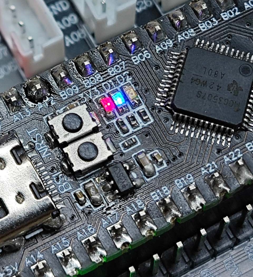
After burning the program, press the NRST button to reset, and then press the K1 button on the expansion board to light up or turn off the D1 silkscreen LED on the core board.
Introduction to MSPM0 robot expansion board
Drive the buzzer

COMPANY

  • About us
  • Team Style
  • Blog

LEARNING & EXPLORATION

  • Tutorials
  • Edge AI hardware
  • Educational robots
  • Embedded intelligent hardware

WHERE TO BUY

  • Yahboom Online Store
  • Amazon
  • Alibaba
  • AliExpress
  • Mercado

TECHNOLOGY SUPPORT

  • Email: support@yahboom.com

BE A DISTRIBUTOR

  • Email: sales@yahboom.com
QR Code

Copyright © 2017-2026 Yahboom. All Rights Reserved.

EN/中文