Welcome to Wheeled Chassis Kit repository
12.K210-Color Reaction
K210-Color Reaction
K210-Color Reaction1. Opening Notes2. Experimental PreparationThe relationship between the 4 motor interfaces and the car is as follows:Hardware wiring:Overall wiringWiring pins3. Key code analysis4. Experimental operation5. Experimental phenomenon
1. Opening Notes
Please read the "Introduction to Motors and Usage" in the information of the four-way motor driver board first to understand the motor parameters, wiring methods, and power supply voltage you are currently using. To avoid burning the motherboard or motor.
Motor: The case and code take the 310 motor of our store as an example.
2. Experimental Preparation
National Race Chassis V2 Four-wheel Drive Version, 4*310 Motors, 7.4V Lithium Battery, K210 Vision Module, Light Bar, STM32F103C8T6 Core Board.
The relationship between the 4 motor interfaces and the car is as follows:
M1 -> upper left motor (left front wheel of the car)
M2 -> lower left motor (left rear wheel of the car)
M3 -> upper right motor (right front wheel of the car)
M4 -> lower right motor (right rear wheel of the car)
Hardware wiring:
Overall wiring
This case does not have a drive motor, so the motor can be left unconnected.
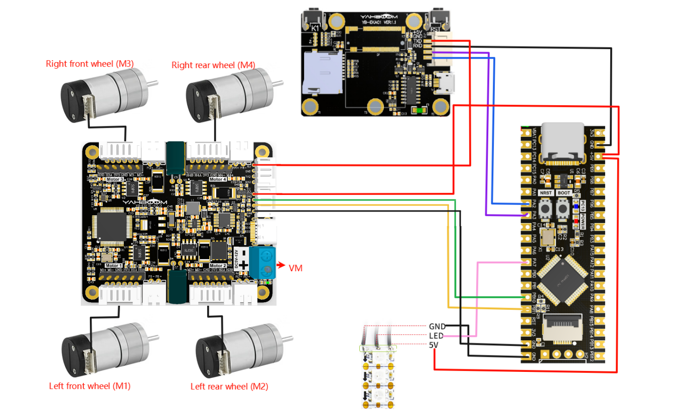
Wiring pins
| Four-way motor driver board | STM32C8T6 |
|---|---|
| 5V | 5V |
| GND | GND |
| SCL | PB10 |
| SDA | PB11 |
Below, take the M1 motor as an example, and other motors are similar
| Motor | Four-way motor driver board (Motor) |
|---|---|
| M2 | M1- |
| VCC | 3V3 |
| A | H1A |
| B | H1B |
| GND | GND |
| M1 | M1+ |
| K210 | STM32C8T6 |
|---|---|
| 5V | 5V |
| GND | GND |
| TXD | PA3 |
| RXD | PA2 |
3. Key code analysis
bsp.c
xvoid BSP_init(void){ SystemInit(); NVIC_PriorityGroupConfig(NVIC_PriorityGroup_2); delay_init();// delay_ms(1000); //等待红外稳定 Wait for infrared to stabilize USART1_init(115200); USART2_init(115200);//使用串口2 接收红外 Use serial port 2 to receive infrared RGB_Init(); IIC_Motor_Init();//四路电机通信初始化 Four-way motor communication initialization
//放到最后才生效,不然还是无法正常使用 It will take effect at the end, otherwise it will not work properly. RCC_APB2PeriphClockCmd(RCC_APB2Periph_AFIO, ENABLE); GPIO_PinRemapConfig(GPIO_Remap_SWJ_JTAGDisable, ENABLE);//禁用jlink 只用SWD调试口,PA15、PB3、4做普通IO Disable jlink and use only SWD debug port, PA15, PB3, 4 as normal IO }The BSP_init() function is the key entry point for system initialization. First, the system clock is initialized through SystemInit(), and then the interrupt priority group is configured as group 2. Then the delay function, serial port (USART1 is used for debugging, USART2 is used to receive infrared signals), RGB light module, and IIC communication interface for four-way motor control are initialized in turn. Finally, the multiplexing function is enabled and JTAG is remapped to SWD, and the PA15, PB3, and PB4 pins are released for use as ordinary GPIOs to ensure that all peripherals work normally and are ready to run the main application.
revaction.c
xxxxxxxxxx// 获取命令标志 Get command flaguint8_t Get_CMD_Flag(void){ return New_CMD_flag;}
...
// 清除命令数据和相关标志 Clear command data and related flagsvoid Clear_CMD_Flag(void){ for (uint8_t i = 0; i < New_CMD_length; i++) { RxBuffer[i] = 0; } New_CMD_length = 0; New_CMD_flag = 0;}
... //数据分析 data analysisvoid Upper_Data_Parse(uint8_t *data_buf, uint8_t num){ uint8_t func_id = *(data_buf + 3); switch (func_id) { /* 判断功能字:小车速度设置 Judgment function word: Trolley speed setting */ case FUNC_MOTION: { ... }
/* 判断功能字:彩灯控制 Judgment function word: color light control */ case FUNC_RGB: { u8 index = *(data_buf + 4); u8 red = *(data_buf + 5); u8 green = *(data_buf + 6); u8 blue = *(data_buf + 7);// printf("RED:%d, G:%d, B:%d\r\n",red,green,blue); RGB_Set_Color(index, red, green, blue); RGB_Update(); break; } default: break; }}The Get_CMD_Flag function returns the current command flag New_CMD_flag, which is used to check whether there is a new command; the Clear_CMD_Flag function clears the command flag and the data in the receiving buffer.
The Upper_Data_Parse function parses the data sent by the upper layer, performs different operations according to different function words (func_id), and FUNC_MOTION extracts the light index and the values of the three RGB color channels in the command, and calls RGB_Set_Color() to set the color, and then uses RGB_Update() to update the display to realize the color light control function.
main.c
xxxxxxxxxx//1:520电机 2:310电机 3:测速码盘TT电机 4:TT直流减速电机 5:L型520电机 //1:520 motor 2:310 motor 3:speed code disc TT motor 4:TT DC reduction motor 5:L type 520 motor
int main(void){ //硬件初始化 Hardware Initialization BSP_init(); ... Set_motor_type(2);//配置电机类型 Configure motor type delay_ms(100); Set_Pluse_Phase(20);//配置减速比 查电机手册得出 Configure the reduction ratio. Check the motor manual to find out delay_ms(100); Set_Pluse_line(13);//配置磁环线 查电机手册得出 Configure the magnetic ring wire. Check the motor manual to get the result. delay_ms(100); Set_Wheel_dis(48.00);//配置轮子直径,测量得出 Configure the wheel diameter and measure it delay_ms(100); Set_motor_deadzone(1300);//配置电机死区,实验得出 Configure the motor dead zone, and the experiment shows delay_ms(100); ... while(1) { if (Get_CMD_Flag()) { Upper_Data_Parse(Get_RxBuffer(), Get_CMD_Length()); Clear_CMD_Flag(); } }}MOTOR_TYPE: used to set the motor type to be used. Modify the corresponding number according to the comments based on the motor you are currently using.
Call the BSP_init() function to initialize the hardware settings, and use Set_Motor(MOTOR_TYPE) to set the motor type and parameters. In the while(1) loop, Get_CMD_Flag detects whether there is a new command. If so, call Upper_Data_Parse to parse the data and set the RGB light color. After processing, use Clear_CMD_Flag to clear the command flag to ensure that the system continues to respond to the host computer instructions.
4. Experimental operation
Burn the program to STM32.
Download the car drive library and PID control library in the K210\library directory to the root directory of the memory card in advance.
Open the color_rgb.py code with CanMV IDE.
Please uncomment
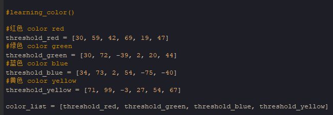
learning_color, then run the program again in CanMV IDE, put the color to be recognized into the box for learning, and wait for the learning to be completed. The serial terminal and display at the bottom of the IDE will display the recognized color value, and replace the recognized color value with the corresponding color value.
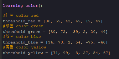
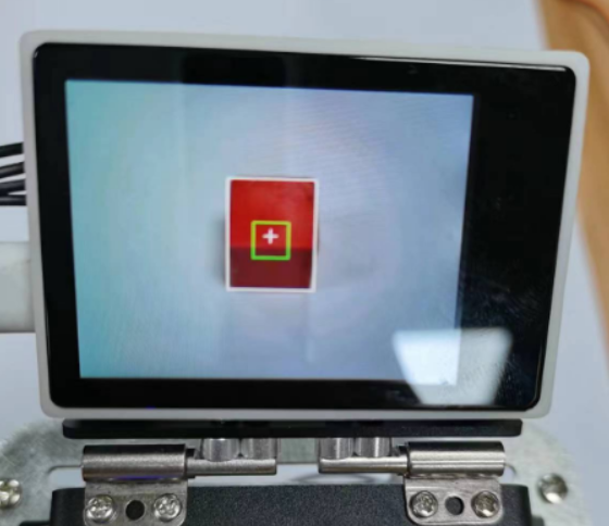
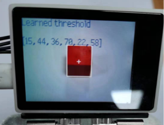
Run the program four times in sequence, and update the values of threshold_red, threshold_green, threshold_blue, and threshold_yellow in sequence. After color learning is completed, comment out the
learning_colorfunction again.
Download the program into the K210 module and run it.
Connect all the wires of the car.
Place the car in a white background, move the K210 module bracket to a suitable angle, and connect the power supply.
5. Experimental phenomenon
After waiting for the system to initialize, please put a red, green, blue or yellow color block in front of the camera's view. The car will automatically light up the corresponding color according to the color of the current color block. If there are multiple color blocks, the car's RGB light will show a marquee effect.