Welcome to Wheeled Chassis Kit repository
1. Turn on the LED light
Light up the LED
Light up the LED1. Learning objectives2. Hardware construction3. Experimental steps1. Open the SYSCONFIG configuration tool2. Parameter settings2.1 Set port parameters2.2 Set pin parameters2.3 Save and update the configuration file3. Write the program4. Compile4. Program Analysis5. Experimental phenomenon
1. Learning objectives
- Learn the basic use of the pins of the MSPM0G3507 motherboard.
- Understand how to control the onboard LED lights.
2. Hardware construction
This course does not require additional hardware equipment, and can directly use the onboard LED lights on the MSPM0G3507 motherboard.
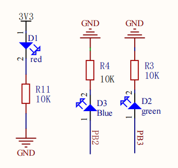
We set up two LED user lights on the motherboard, and users can DIY their functions. Take LED1 as an example below.
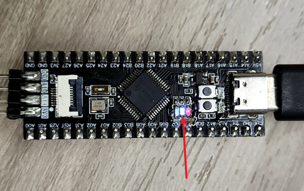
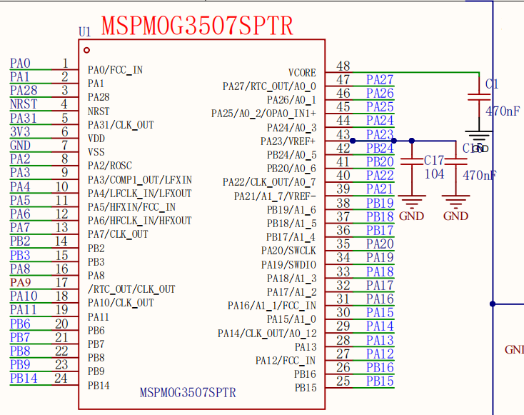
MSPM0G3507 main control diagram
LED schematic diagram
3. Experimental steps
1. Open the SYSCONFIG configuration tool
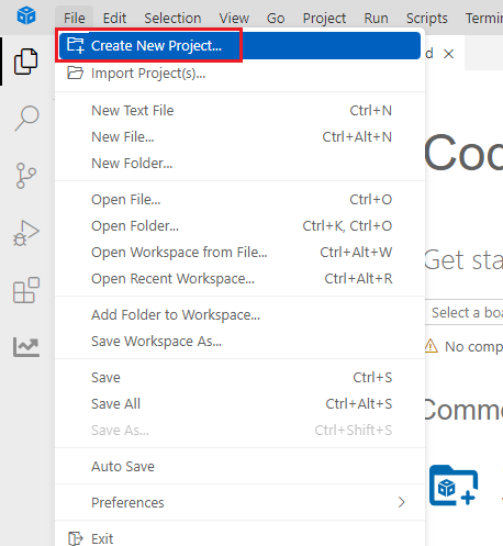
Create a blank project empty in CCS.
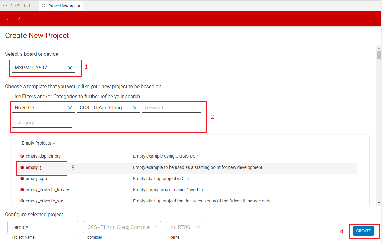
Find and open the empty.syscfg file in the left workspace of CCS.
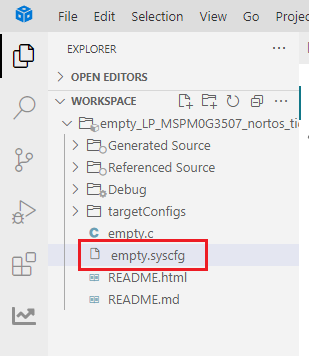
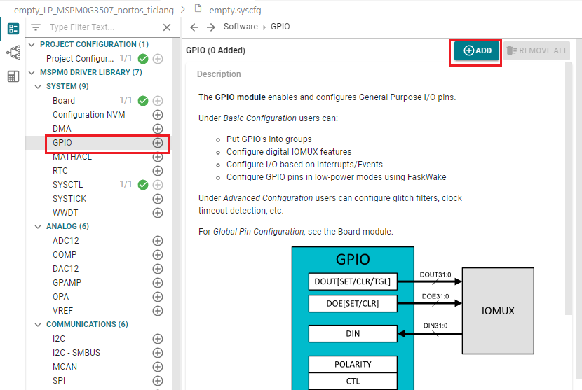
In SYSCONFIG, select MCU peripherals on the left, find the GPIO option and click to enter. Click ADD in GPIO to add a group of GPIO.
2. Parameter settings
2.1 Set port parameters
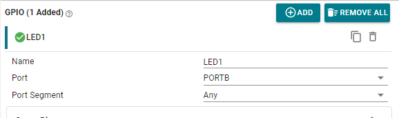
Set GPIO parameters and name the pin LED1
From the LED schematic, we can see that the port where LED1 is located is PB2, so set the Port to PORTB.
Parameter description:
Name: Custom name of the GPIO instance. By default, the name starts with a numeric suffix "0"; we can customize the name to reflect the purpose of the module (for example, name the GPIO "LED1" so that we know that this pin is specifically used to control LED1).
Port: The port where the GPIO instance is located. The LED is connected to the GPIOB2 pin, so only PORTB can be selected.
Port Segment: Set the pull-up and pull-down resistors on the port. Note that it is the pull-up and pull-down of the port, which sets the entire GPIOB port.
2.2 Set pin parameters
Set the pin to output mode, set the pin to output low level by default, set the pin to pull-down mode, set the pin to GPIOB_2 pin, and do not enable interrupt events.
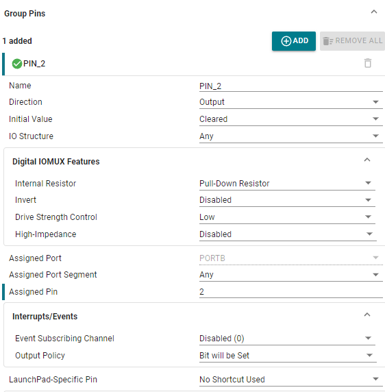
Parameter description:
Name: User-defined pin name, set to PIN_2.
Direction: Set the pin mode, input and output. Here we control the LED light and choose the output mode.
Initial Value: Set the initial state of the pin, which can only be set when configured as output mode. There are two options, clear and set. Clear means output low level, and set means output high level.
IO Structure: Set the IO structure. There are multiple options, including Any, Standard, Standard with Wake, High-Speed, and 5V Tolerant Open Drain.
Internal Resistor: Set the pull-up and pull-down resistors of the pin. There are three options, no pull-up, pull-up, and pull-down. Here, the pull-down resistor is selected according to the connection method of the LED light.
Assigned Pin: Set the pin number. Fill in the corresponding pin number for the pin to be controlled. For example, if the LED in the development board is connected to GPIOB2, fill in 2.
2.3 Save and update the configuration file
Save the configuration in the .syscfg file using the shortcut key Ctrl+S.
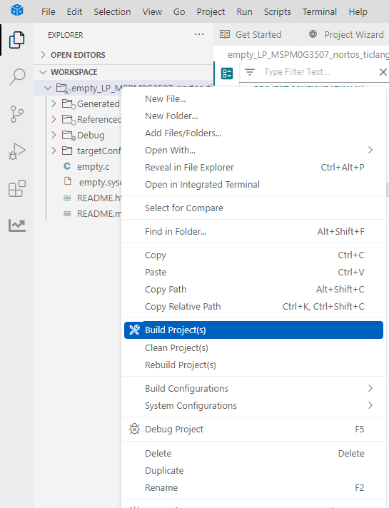
Compile after saving
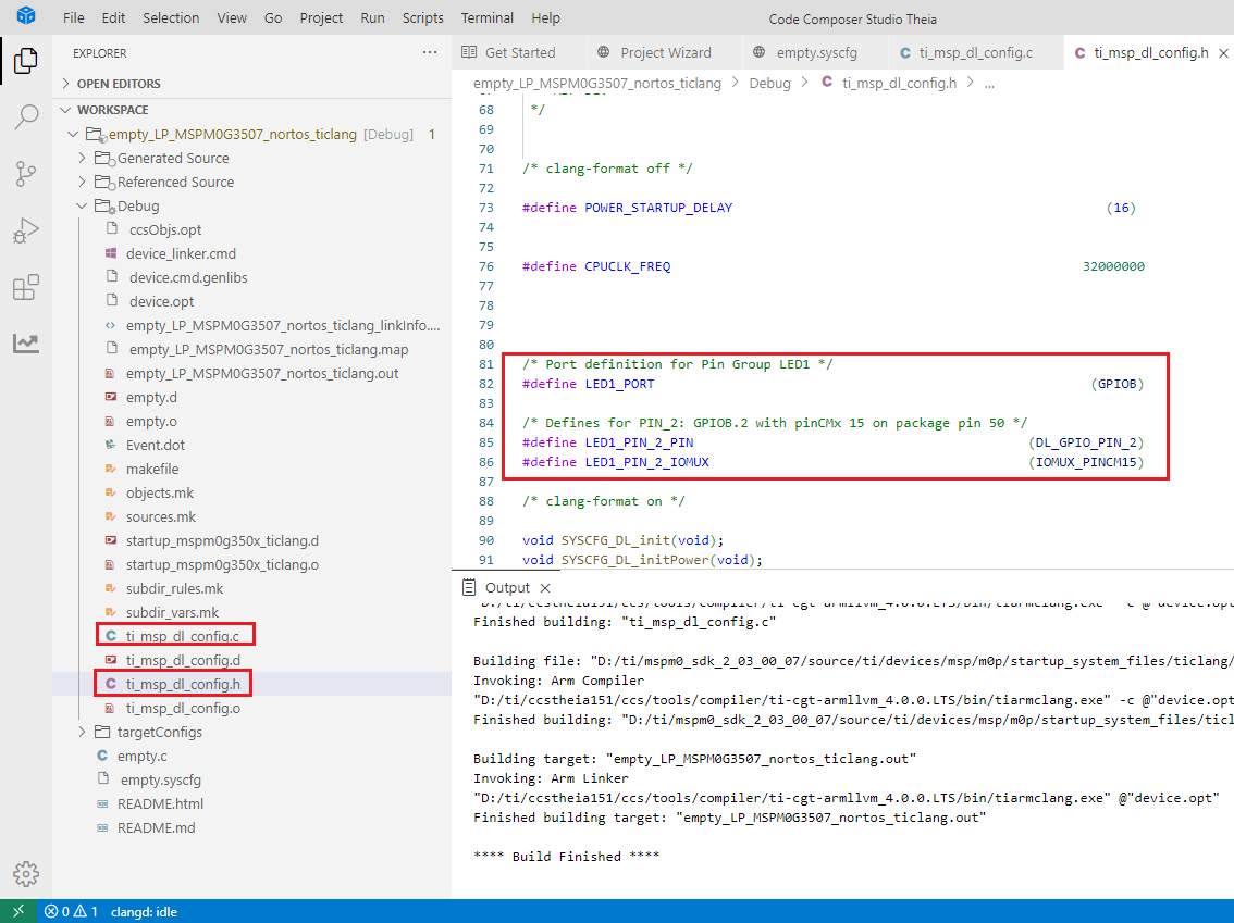
After compiling, we can see that there are two more files in the Debug folder, ti_msp_dl_config.c and ti_msp_dl_config.h. These two files are the peripheral low-level driver configuration codes generated based on the .sysfig file we just saved.
3. Write the program
In the empty.c file, write the following code
x#include "ti_msp_dl_config.h"//自定义延时(不精确) Custom delay (not precise)void delay_ms(unsigned int ms){ unsigned int i, j; // 下面的嵌套循环的次数是根据主控频率和编译器生成的指令周期大致计算出来的, // 需要通过实际测试调整来达到所需的延时。 // The number of nested loops below is roughly calculated based on the master control frequency and the instruction cycle generated by the compiler,and needs to be adjusted through actual testing to achieve the required delay. for (i = 0; i < ms; i++) { for (j = 0; j < 8000; j++) { // 仅执行一个足够简单以致于可以预测其执行时间的操作 // Perform only one operation that is simple enough to predict its execution time __asm__("nop"); // "nop" 代表“无操作”,在大多数架构中,这会消耗一个或几个时钟周期 "nop" stands for "no operation", which on most architectures consumes one or a few clock cycles } }}int main(void){ SYSCFG_DL_init(); while (1) { DL_GPIO_clearPins(LED1_PORT,LED1_PIN_2_PIN);//输出低电平 Output low level delay_ms(1000);//延时大概1S Delay about 1S DL_GPIO_setPins(LED1_PORT,LED1_PIN_2_PIN); //输出高电平 Output high level delay_ms(1000);//延时大概1S Delay about 1S }}4. Compile
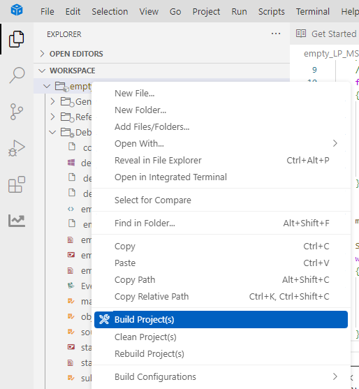
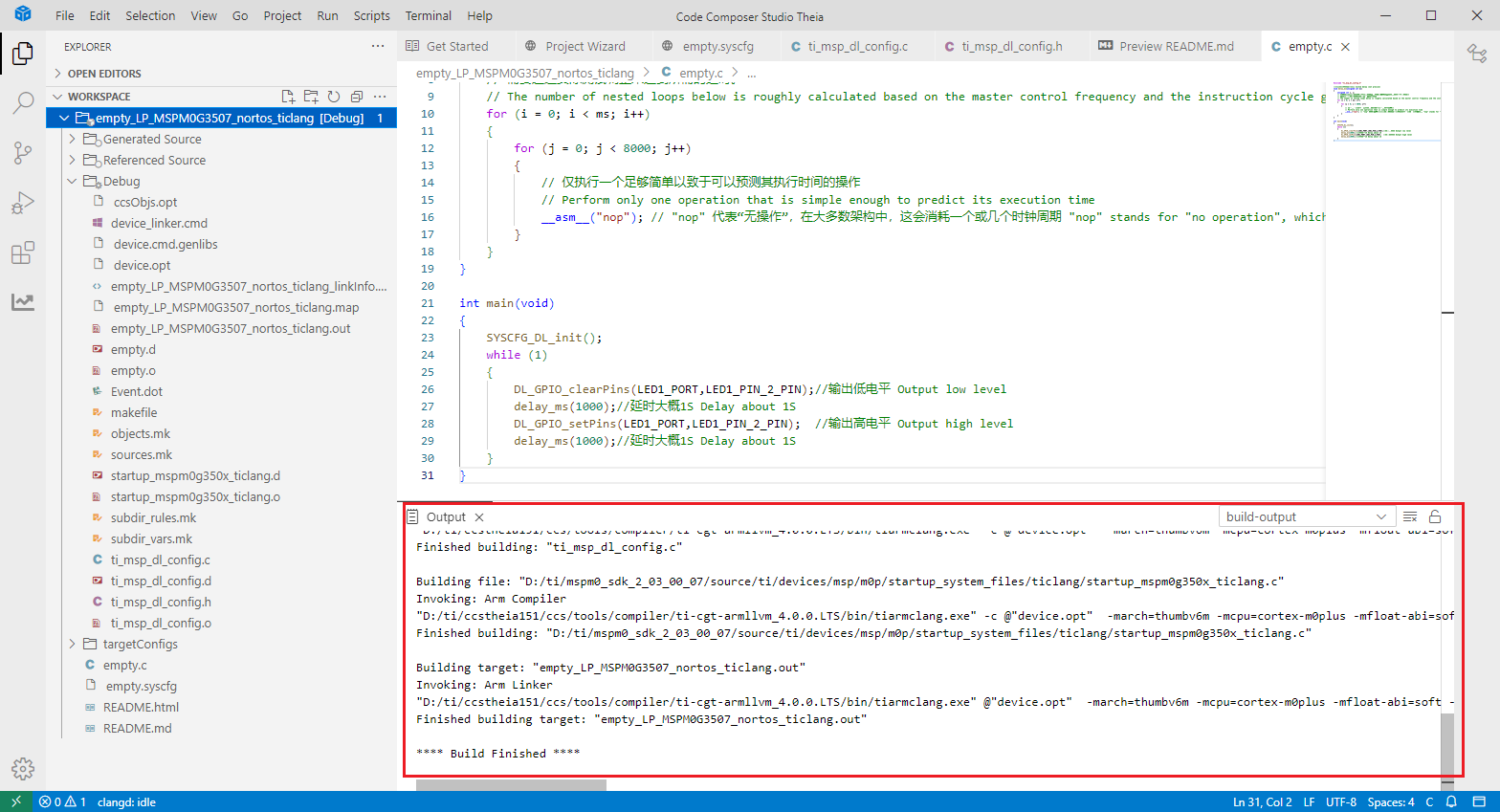
It shows that the compilation is successful here, and the program can be downloaded to the development board.
4. Program Analysis
- dl_gpio.h
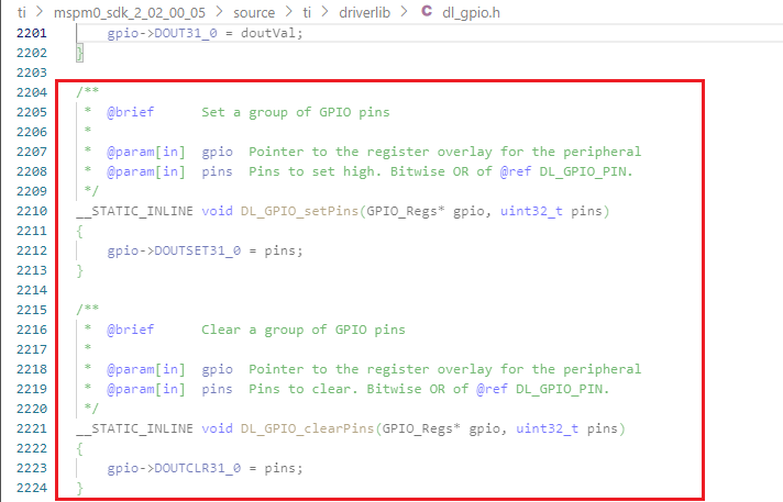
__STATIC_INLINE void DL_GPIO_setPins(GPIO_Regs* gpio, uint32_t pins): This function is to control the pin to output a high level.
__STATIC_INLINE void DL_GPIO_clearPins(GPIO_Regs* gpio, uint32_t pins): This function is used to control the pin to output a low level.
- empty.c
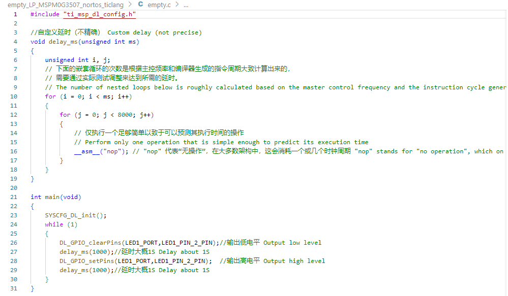
Using an imprecise delay, set PB2 to output a low level, and then output a high level after a delay of about 1s, and then delay for about 1s. This process is repeated.
5. Experimental phenomenon
After the program is downloaded, you can see that the LED1 on the MSPM0 development board is lit and flashes every about 1s.