Welcome to Wheeled Chassis Kit repository
17.K230-Color tracking
Color Tracking
1. Opening Statement
The motor driver board used in this case is the four-way motor driver board of Yaboom. If you use this driver board, please read the "Motor Introduction and Usage" in the four-way motor driver board document first to understand the motor parameters, wiring method, and power supply voltage you are currently using. This will avoid burning out the motherboard or motor.
2. Experimental Preparation
Wheeled car chassis, 4*L520 motors, 12V lithium battery, K230 vision module, Yaboom MSPM0G3507 core board.
The relationship between the 4 motor interfaces and the car is as follows:
M1 -> Upper left motor (left front wheel of the car) M3 -> upper right motor (right front wheel of the car)
M2 -> Lower left motor (left rear wheel of the car) M4 -> Lower right motor (right rear wheel of the car)
Hardware Wiring
.png)
Wiring Pins
| Four-way motor driver board | MSPM0G3507 |
|---|---|
| 5V | 5V |
| GND | GND |
| RX2 | PB6 |
| TX2 | PB7 |
The following takes the M1 motor as an example, and other motors are similar:
| Motor | Four-way motor driver board (Motor) |
|---|---|
| M2 | M1- |
| VCC | 3V3 |
| A | H1A |
| B | H1B |
| GND | GND |
| M1 | M1+ |
| K230 | MSPM0G3507 |
|---|---|
| 5V | 5V |
| GND | GND |
| TXD | PA25 |
| RXD | PA26 |
3. Experimental Operation
Follow the hardware wiring instructions in the tutorial to connect.
Open the ProtocolHub project used by MSPM0G3507, first check the beginning of the main.c file. The first thing to do is to change the number of MOTOR_TYPE to the motor you are using, and the second is to change color_mode to 2 to turn on the color tracking mode. After these two places are modified correctly, compile and burn, and finally reset or power on again.
Place color_track.py in the root directory of K230's sdcard and rename it to main.py, then reset or power on.
If you are not sure how to burn the program into K230, please read the K230 Quick Start tutorial first.
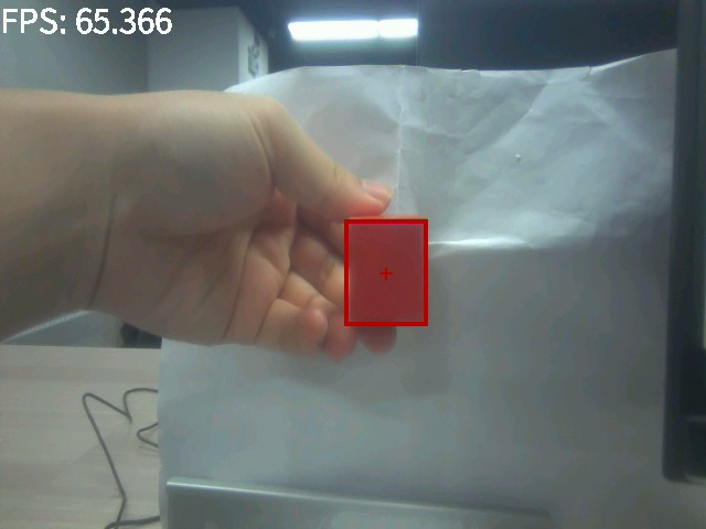
Bend the K230 module bracket to a suitable angle and connect the power supply. Place a brightly colored object in front of the K230 camera.
After K230 is initialized successfully, it will start to recognize the set color. After waiting for three seconds, the robot will start tracking.
Notice:
color_track.py provides recognition of four preset colors: red, green, blue, and yellow. If the recognition effect is not good, you can watch the K230 color recognition tutorial to learn how to change the LAB threshold to a threshold that suits your environment.
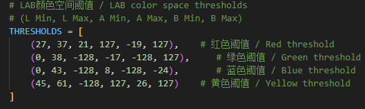
Here you can change it to the color you want to track:

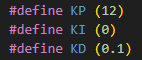
If you are not satisfied with the tracking effect, you can modify the PID value of the app_motor.c file in the ProtocolHub project.
4. Code analysis
main.c
x//1:520电机 2:310电机 3:测速码盘TT电机 4:TT直流减速电机 5:L型520电机 //1:520 motor 2:310 motor 3:speed code disc TT motor 4:TT DC reduction motor 5:L type 520 motor
//修改当前要运行的颜色案例 Modify the color case currently being runColorMode color_mode = 1; //1:巡线、2:跟踪 1: Patrol, 2: Tracking
//选择是否在初始化完成后,小车自主向前走,0为否,1为是(自主避让案例使用)//Select whether the car moves forward autonomously after initialization is completed, 0 for no, 1 for yes (used in autonomous avoidance cases)int Car_Auto_Drive = 0;
int main(void){ USART_Init();
//使能DMA通道,用于加快与四路电机驱动板串口的通讯 Enable DMA channel to speed up communication with the serial port of the four-way motor driver board NVIC_ClearPendingIRQ(UART_1_INST_INT_IRQN); DL_DMA_enableChannel(DMA, DMA_CH0_CHAN_ID); NVIC_EnableIRQ(UART_1_INST_INT_IRQN); //开启与K230串口通信的中断 Enable interrupts for communication with the K230 serial port NVIC_ClearPendingIRQ(UART_3_INST_INT_IRQN); NVIC_EnableIRQ(UART_3_INST_INT_IRQN); //设置电机类型 Set motor type Set_Motor(MOTOR_TYPE);
if(Car_Auto_Drive)//K230上电初始化需要时间,等待初始化完成之后再开始前进。 It takes time for K230 to power on and initialize. Wait until the initialization is complete before moving forward. { delay_ms(1000);delay_ms(1000);delay_ms(1000);delay_ms(1000);delay_ms(1000);delay_ms(1000);delay_ms(1000);delay_ms(1000);delay_ms(1000);delay_ms(1000); } printf("Init Succeed\r\n"); while(1) { Pto_Loop(); delay_ms(10); }}MOTOR_TYPE: Used to set the motor type to be used. Modify the corresponding number according to the comments based on the motor you are currently using.
color_mode: Use 1 when running the visual line patrol case, and use 2 for the color tracking case
Car_Auto_Drive: Controls the car to move forward automatically after initialization. The default value is 0, which means the car does not move forward automatically. This function only needs to be enabled when using the autonomous avoidance case.
USART_Init: initialization function of system and serial port.
Set_Motor: Communicate with the four-way motor driver board and set motor related parameters
Pto_Loop: Continuously processes the received K230 messages.
yb_protocol.c
xxxxxxxxxx/** * @Brief: 数据分析 Data analysis * @Note:  * @Parm: 传入接受到的一个数据帧和长度    Pass in a received data frame and length * @Retval:  */void Pto_Data_Parse(uint8_t *data_buf, uint8_t num){    uint8_t pto_head = data_buf[0];    uint8_t pto_tail = data_buf[num-1];        //校验头尾  Check head and tail    if (!(pto_head == PTO_HEAD && pto_tail == PTO_TAIL))    {        //DEBUG_PRINT("pto error:pto_head=0x%02x , pto_tail=0x%02x\n", pto_head, pto_tail);        return;    }        uint8_t data_index = 1;    uint8_t field_index[PTO_BUF_LEN_MAX] = {0};    int i = 0;    int values[PTO_BUF_LEN_MAX] = {0};    char msgs[][PTO_BUF_LEN_MAX] = {0};        //分割字段  Split Field    for (i = 1; i < num-1; i++)    {        if (data_buf[i] == ',')        {            data_buf[i] = 0;            field_index[data_index] = i;            data_index++;        }    }        //解析长度与功能ID  Parsing length and function ID    for (i = 0; i < 2; i++)    {        values[i] = Pto_Char_To_Int((char*)data_buf+field_index[i]+1);    }        uint8_t pto_len = values[0];    uint8_t pto_id = values[1];        ParseCommonFields(pto_id,data_buf,pto_len,field_index,data_index,values,msgs);}

//获取数据函数  Get data functionvoid ParseCommonFields(    int func_index,       // 功能索引(对应func_table中的位置) Function index (corresponding to the position in func_table)    uint8_t *data_buf,    // 原始数据缓冲区 Raw data buffer    uint8_t num,          // 数据总长度(含头尾)   Total length of data (including head and tail)    uint8_t *field_index, // 字段分隔符位置数组(逗号的位置)   Array of field separator positions (positions of commas)    uint8_t data_index,   // 总字段数(如数据有6个字段)    Total number of fields (if the data has 6 fields)    int* values,          // 存储整数字段的数组 Array to store integer fields    char msgs[][PTO_BUF_LEN_MAX]        // 存储字符串的指针数组 Array of pointers to store strings){    const FuncDesc* desc = &func_table[func_index-1];        if(func_index != desc->id)    {        DEBUG_PRINT("Unsupported protocol ID: %d, Chosen ID:%d\n", func_index,desc->id);        return;    }        for (int i = 0; i < desc->field_count; i++)     {        const FieldMeta* meta = &desc->fields[i];        uint8_t pos = meta->pos;                if (meta->type == FIELD_STRING) {            int start = field_index[pos] + 1;            int end = (pos+1 < data_index) ? field_index[pos+1] : (num-1);            int len = end - start;                        len = (len < PTO_BUF_LEN_MAX-1) ? len : PTO_BUF_LEN_MAX-1;            memcpy(msgs[i], data_buf+start, len);            msgs[i][len] = '\0';        } else {            values[pos] = Pto_Char_To_Int((char*)data_buf + field_index[pos] +1);        }    }    desc->handler(values, msgs);}
Parse the received data that conforms to the protocol, obtain the function ID number and the data information carried in the data, and execute the processing function of the corresponding function. This project uses the metadata parsing method. The core idea is to separate the description of the protocol format (field position, type, etc.) from the parsing logic, define the protocol format through data structures (such as structure arrays), and the parsing function automatically processes the data based on these descriptions.
The protocol contains different types of data that can also be parsed. If you want to know the implementation details, you can study it yourself. I won't give too many answers. This function has been adapted to all K230 communication protocols in our store, and you can use it normally without fully understanding it.
bsp_motor_iic.c
xxxxxxxxxx//只能控制带编码器类型的电机 Can only control motors with encoders//传入参数:4个电机的速度      Input parameters: speed of 4 motorsvoid control_speed(int16_t m1,int16_t m2 ,int16_t m3,int16_t m4){    static uint8_t speed[8];        speed[0] = (m1>>8)&0xff;    speed[1] = (m1)&0xff;        speed[2] = (m2>>8)&0xff;    speed[3] = (m2)&0xff;        speed[4] = (m3>>8)&0xff;    speed[5] = (m3)&0xff;        speed[6] = (m4>>8)&0xff;    speed[7] = (m4)&0xff;        i2cWrite(Motor_model_ADDR,SPEED_Control_REG,8,speed);

}

//控制带编码器类型的电机   Control the motor with encoder type//传入参数:4个电机的pwm PWM of 4 motors//此函数可以结合实时编码器的数据,来实现control_speed的功能   This function can combine the data of real-time encoder to realize the function of control_speedvoid control_pwm(int16_t m1,int16_t m2 ,int16_t m3,int16_t m4){    static uint8_t pwm[8];        pwm[0] = (m1>>8)&0xff;    pwm[1] = (m1)&0xff;        pwm[2] = (m2>>8)&0xff;    pwm[3] = (m2)&0xff;        pwm[4] = (m3>>8)&0xff;    pwm[5] = (m3)&0xff;        pwm[6] = (m4>>8)&0xff;    pwm[7] = (m4)&0xff;        i2cWrite(Motor_model_ADDR,PWM_Control_REG,8,pwm);

}
control_speed : Controls the speed of the motor. It splits the four motor speed values into high and low bytes, and then sends them to the motor controller via the I2C protocol to set the motor speed.
control_pwm : controls the PWM (pulse width modulation) value of the motor. It splits the incoming PWM values of the four motors into high and low bytes and sends them to the motor controller via the I2C protocol to control the speed and direction of the motor.
app_engine.c
xxxxxxxxxx//控制小车运行,输入的参数分别为x、y、z三个轴上的速度值//Control the movement of the car. The input parameters are the speed values on the x, y, and z axes.void Motion_Car_Control(int16_t V_x, int16_t V_y, int16_t V_z){    float robot_APB = Motion_Get_APB();    speed_lr = 0;    speed_fb = V_x;    speed_spin = (V_z / 1000.0f) * robot_APB;    if (V_x == 0 && V_y == 0 && V_z == 0)    {        control_pwm(0,0,0,0);        return;    }

    speed_L1_setup = speed_fb - speed_spin;    speed_L2_setup = speed_fb - speed_spin;    speed_R1_setup = speed_fb  + speed_spin;    speed_R2_setup = speed_fb  + speed_spin;            if (speed_L1_setup > 1000) speed_L1_setup = 1000;    if (speed_L1_setup < -1000) speed_L1_setup = -1000;    if (speed_L2_setup > 1000) speed_L2_setup = 1000;    if (speed_L2_setup < -1000) speed_L2_setup = -1000;    if (speed_R1_setup > 1000) speed_R1_setup = 1000;    if (speed_R1_setup < -1000) speed_R1_setup = -1000;    if (speed_R2_setup > 1000) speed_R2_setup = 1000;    if (speed_R2_setup < -1000) speed_R2_setup = -1000;        //DEBUG_PRINT("L1:%d, L2:%d, L3:%d, L4:%d\r\n",speed_L1_setup,speed_L2_setup,speed_R1_setup,speed_R2_setup);    //DEBUG_PRINT("\r\n");    if(PWM_Car_Flag)//如果小车是无编码器类型的,就直接控制pwm,否则控制速度 If the car is encoderless, it controls PWM directly, otherwise it controls the speed    {        control_pwm(speed_L1_setup, speed_L2_setup, speed_R1_setup, speed_R2_setup);    }    else    {        control_speed(speed_L1_setup, speed_L2_setup, speed_R1_setup, speed_R2_setup);    }}

void Color_Trace(int x,int w,int h){    if(!Wait_Flag)    {        delay_ms(1000);delay_ms(1000);delay_ms(1000);//delay 3s        Wait_Flag = 1;        return;    }        if(Wait_Flag && !SetTarget_Flag)    {        SetTarget_Flag = 1;        target_area = w*h/100;    }

    int now_area = w*h/100;        int16_t err = 280 - x;    DEBUG_PRINT("x:%d, CENTER:%d\r\n", x, 280);    DEBUG_PRINT("err:%d\r\n", err);        pid_output = PID_Calc(err);    DEBUG_PRINT("pid_output:%d\r\n", pid_output);    if(pid_output>500) pid_output=500;//对pid输出值进行限幅,防止小车跑过头   Limit the pid output value to prevent the car from running too far    if(pid_output<-500) pid_output=-500;        DEBUG_PRINT("\r\n");        int16_t err_area = target_area - now_area;//计算要追踪的面积差值    Calculate the difference in area to be tracked    DEBUG_PRINT("now_area:%d, target_area:%d\r\n", now_area, target_area);    DEBUG_PRINT("err_area:%d\r\n", err_area);        if(err_area<10 && err_area>-10)err_area=0;//设置要追踪的面积限幅,减少因为微弱变化而引起小车频繁的抖动  Set the area limit to be tracked to reduce the frequent shaking of the car caused by slight changes    pid_output1 = PID_Calc(err_area);    DEBUG_PRINT("pid_output1:%d\r\n", pid_output1);    if(pid_output1>200) pid_output1=200;//对pid输出值进行限幅,防止小车跑过头   Limit the pid output value to prevent the car from running too far    if(pid_output1<-200) pid_output1=-200;        DEBUG_PRINT("\r\n");            Motion_Car_Control(pid_output1, 0, pid_output);}
Motion_Car_Control: A function used to control the car. The input parameter value will be used to control the speed of the motor with encoder, and the motor without encoder will control the pwm value.
Color_Trace: After receiving the data from K230, it will wait for three seconds, then start calculating the x-axis offset and area offset of the recognized color, and finally control the robot.
5. Experimental Phenomenon
Turn on the power switch and wait for the system to initialize. The screen will display the camera image and frame the color you want to track. After waiting for three seconds, the robot will move along the recognized color frame to keep it in the center of the screen.