yahboom
HomeLearn
Solution
Blog
Online Store
About Us
EN/中文
Wheeled Chassis Kit📖
0.Chassis installation course
  • Installation Video-1
  • Installation Video-2
  • Installation Video-3
1.4-channel motor drive module tutorials
Motor introduction and commissioning
  • 1. Motor introduction and usage
  • 2.PC host
IIC communication
  • For Arduino
  • For ESP32
  • For JetsonNANO
  • For MSPM0
  • For PICO2
  • For RDK X5
  • For RPi5
  • For STM32
USART communication
  • For Arduino
  • For ESP32
  • For JetsonNANO
  • For MSPM0
  • For PICO2
  • For RDK X5
  • For RPi5
  • For STM32
2.Kinematic analysis
  • Kinematic Analysis of Two-wheel Drive Vehicles
  • Kinematic Analysis of Four-wheel Drive Vehicles
3.MSPM0 chassis tutorials(MSPM0G3507/MSPM0G3519)
MSPM0 Basic Course
  • 1. Introduction to MSPM0
Development environment construction
  • 01.CCS Theia Development
  • 02.MDK Arm Development
  • 03.UniFlash Downloader
  • 04.DAP-LINK download program
  • 05.Program simulation and debugging
  • 06.Engineering transplantation
Keil basic case
  • 1. Turn on the LED light
  • 2. System delay
  • 3. Button control
  • 4. External interruption
  • 5. Serial communication
  • 6. Timer
  • 7. PWM breathing light
  • 8. ADC acquisition
  • 9. DMA transfer
  • 10. Get MPU6050 data (I2C)
  • 11. LCD Display (SPI)
CCS basic case
  • 1. Turn on the LED light
  • 2. System delay
  • 3. Button control
  • 4. External interruption
  • 5. Serial communication
  • 6. Timer
  • 7. PWM breathing light
  • 8. ADC acquisition
  • 9. DMA transfer
  • 10. Get MPU6050 data (I2C)
  • 11. LCD Display (SPI)
MSPM0 Robot Expansion Board Example
  • 1. Introduction to MSPM0 robot expansion board
  • 2. Customize buttons
  • 3. Drive the buzzer
MSPM0 Sensor extension information
  • 01.3-channel tracking
  • 02.4-channel tracking
  • 03.8-channel tracking
  • 04.CCD tracking
  • 05.Electric PTZ control
  • 06.2.4G handle control
  • 07.Servo ultrasonic avoid
  • 08.Bluetooth remote control
  • 09.K210-Automatic Driving
  • 10.K210-Color follow
  • 11.K210-Number recognition
  • 12.K210-Color reaction
  • 13.K210-Road signs
  • 14.K210-Machine code following
  • 15.K210-QR code recognition
  • 16.K230-Visual tracking
  • 17.K230-Color tracking
  • 18.K230-Color response
  • 19.K230-Road sign recognition
  • 20.K230-Machine code tracking
  • 21.K230-QR code recognition action
  • 22.K230-Autonomous avoid
  • 23.K230-License plate tracking
  • 24.K230-Face tracking
  • 25.K230-Gaze direction tracking
  • 26.K230-Palm tracking
  • 27.K230-Target tracking
  • 28.K230-Human body tracking
  • 29.K230-OCR character recognition action
4.STM32 chassis tutorials
  • 01.3-channel tracking
  • 02.4-channel tracking
  • 03.8-channel tracking
  • 04.CCD tracking
  • 05.Electric PTZ control
  • 06.2.4G handle control
  • 07.Servo ultrasonic avoid
  • 08.Bluetooth remote control
  • 09.K210-Automatic Driving
  • 10.K210-Color follow
  • 11.K210-Number recognition
  • 12.K210-Color Reaction
  • 13.K210-Road signs
  • 14.K210-Machine code following
  • 15.K210-QR code recognition
  • 16.K230-Visual tracking
  • 17.K230-Color tracking
  • 18.K230-Color response
  • 19.K230-Road sign recognition
  • 20.K230-Machine code tracking
  • 21.K230-QR code recognition action
  • 22.K230-Autonomous avoid
  • 23.K230-License plate tracking
  • 24.K230-Face tracking
  • 25.K230-Gaze direction tracking
  • 26.K230-Palm tracking
  • 27.K230-Target tracking
  • 28.K230-Human body tracking
  • 29.K230-OCR character recognition action
5.Expand course
  • 1.Autonomous driving car
  • 2.Vehicle-mounted balance ball motion control systemnew
Download
  • Code
  • 3D_Model_File
Download ZIP

Welcome to Wheeled Chassis Kit repository

08.Bluetooth remote control

Bluetooth control

Bluetooth control1. Introduction2. Experimental preparationThe relationship between the 4 motor interfaces and the car is as follows:Hardware wiring:Wiring using MSPM0 robot expansion boardWiring using MSPM0G3507 core board (Yahboom)Wiring pins3. Key code analysis4. Experimental phenomenon

1. Introduction

Please read the "Introduction to Motors and Usage" in the four-way motor driver board information first to understand the motor parameters, wiring methods, and power supply voltage you are currently using. To avoid burning the motherboard or motor.

2. Experimental preparation

Guo Sai chassis V2 four-wheel drive version, 4*L520 motors, 12V lithium battery, Bluetooth 5.0 module (Yahboom), MSPM0 robot expansion board (optional), MSPM0G3507 core board (Yahboom).

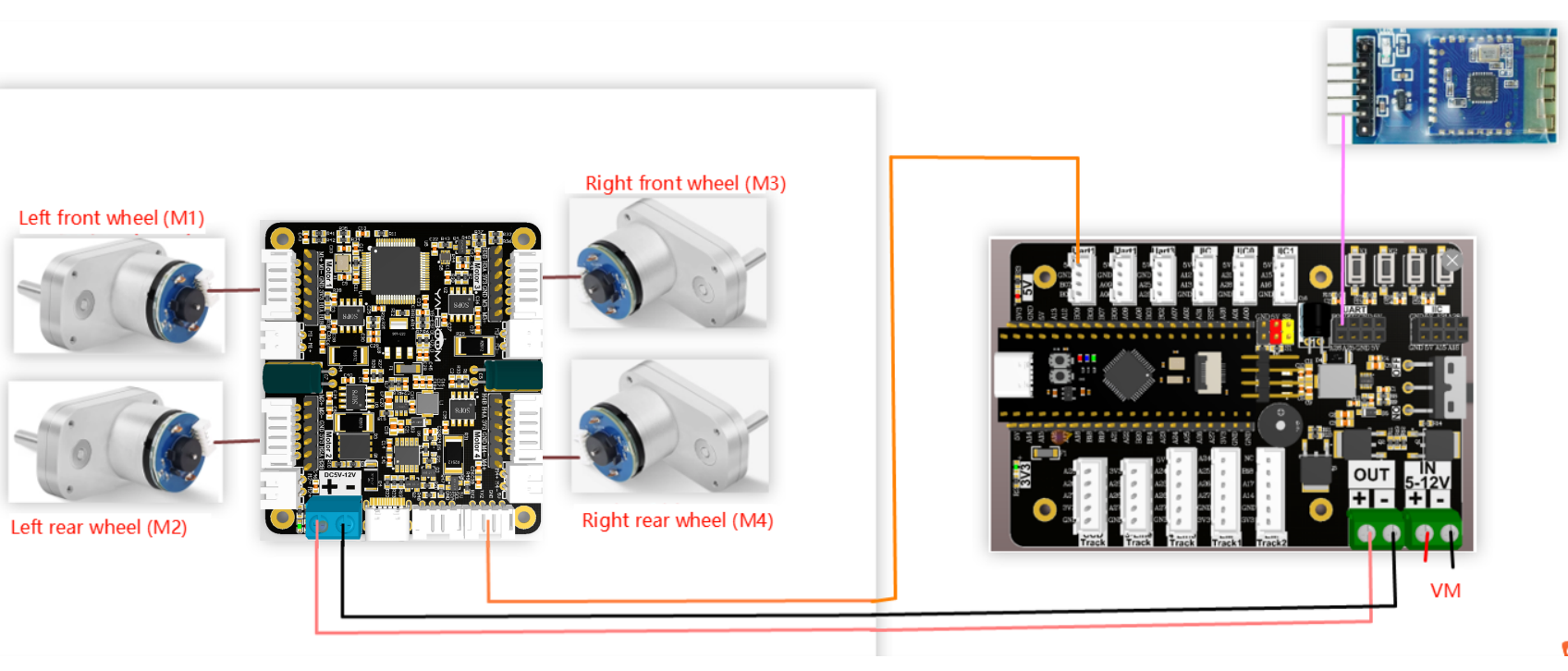
The relationship between the 4 motor interfaces and the car is as follows:

M1 -> upper left motor (left front wheel of the car)

M2 -> lower left motor (left rear wheel of the car)

M3 -> upper right motor (right front wheel of the car)

M4 -> lower right motor (right rear wheel of the car)

Hardware wiring:

Wiring using MSPM0 robot expansion board

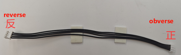
Note: The wire used to connect the MSPM0 robot expansion board to the four-way motor drive module is: XPH2.0-4pin cable, double-ended all black, reverse (200mm), the direction of the reverse cable holder is shown in the figure below
扩展板接线

Wiring using MSPM0G3507 core board (Yahboom)
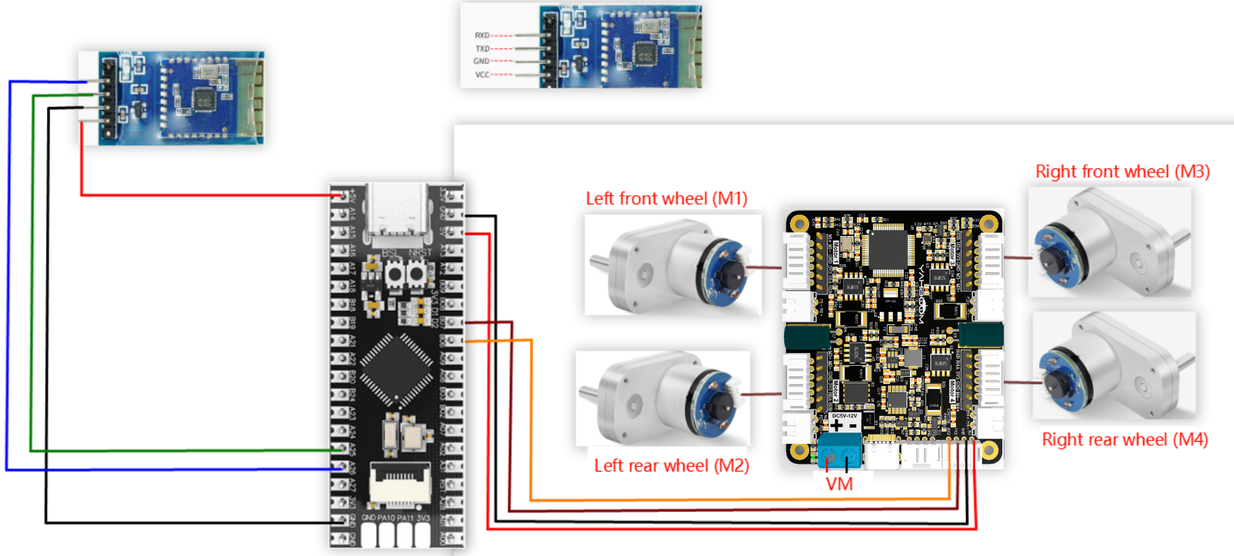
mspban

Wiring pins

Four-way motor driver boardMSPM0G3507 core board (Yahboom)
RX2PB6
TX2PB7
GNDGND
5V5V

Take M1 motor as an example below, and other motors are similar

MotorFour-way motor driver board (Motor)
M+M1+
M-M1-
GNDGND
VCC3V3
BH1A
AH1B
Bluetooth 5.0 module (Yabo)MSPM0G3507 core board (Yahboom)
5V5V
GNDGND
TXDPA25
RXDPA26

3. Key code analysis

  • usart.c

​x
void UART_0_INST_IRQHandler(void)
{
    uint8_t receivedData = 0;
    static uint8_t rec_state = 0;
    
    //如果产生了串口中断
    //If a serial port interrupt occurs
    switch(DL_UART_getPendingInterrupt(UART_0_INST) )
    {
        case DL_UART_IIDX_RX://如果是接收中断  If it is a receive interrupt
            
            // 接收发送过来的数据保存  Receive and save the data sent
            receivedData = DL_UART_Main_receiveData(UART_0_INST);
            switch(rec_state)
            {
                case 0:
                    if((receivedData == '$') && (!recv0_flag))
                    {
                        rec_state = 1;
                        recv0_length = 0;
                    }
                    else 
                    {
                        rec_state = 0;
                    }
                    break;
                case 1:
                    if(receivedData == '#')
                    {
                        recv0_flag = 1;
                        rec_state = 0;
                    }
                    else
                    {
                        recv0_buff[recv0_length++] = receivedData;
                    }
                    break;
            }
            default://其他的串口中断   Other serial port interrupts
            break;
    }
}

UART_0_INST_IRQHandler: Processes the protocol data sent by the app


  • Motor.c

xxxxxxxxxx
void Data_Analyse(void)//解析串口中断串口接收的数据  Parse the data received by the serial port interrupt
{
        if(recv0_flag == 1)
        {
            switch(recv0_buff[0])
            {
                case '1':
                    printf("Forward!\n");
                    Car_state = 1;
                    break;
                case '2':
                    printf("Backward!\n");
                    Car_state = 2;
                    break;
                case '3':
                    printf("Left!\n");
                    Car_state = 3;
                    break;
                case '4':
                    printf("Right!\n");
                    Car_state = 4;
                    break;
                case '0':
                    printf("Stop!\n");
                    Car_state = 0;
                    break;
            }
            switch(recv0_buff[2])
            {
                case '1':
                    printf("SpinLeft!\n");
                    Car_state = 5;
                    break;
                case '2':
                    printf("SpinRight!\n");
                    Car_state = 6;
                    break;
            }
            recv0_flag = 0;
        }           
}
void Car_Function(unsigned int Car_state)//控制小车不同状态 Control the car in different states
{
    switch(Car_state)
    {
            case 0:
                    printf("Stop\n");
                    Stop();
                    break;
            case 1:
                    printf("Forward\n");
                    Forward(2300);
                    break;
            case 2:
                    printf("Backward\n");
                    Backward(2300);
                    break;
            case 3:
                    printf("Turnleft\n");
                    Turnleft(2500);
                    break;
            case 4:
                    printf("Turnright\n");
                    Turnright(2500);
                    break;
            case 5:
                    printf("SpinLeft\n");
                    SpinLeft(2500);
                    break;
            case 6:
                    printf("SpinRight\n");
                    SpinRight(2500);
                    break;
    }
}
void Forward(int Speed)
{
    Contrl_Pwm(1000,1000,1000,1000);
}
void Backward(int Speed)
{
    Contrl_Pwm(-1000,-1000,-1000,-1000);
}
void Turnleft(int Speed)
{
    Contrl_Pwm(0,0,1200,1200);
}
void Turnright(int Speed)
{
    Contrl_Pwm(1200,1200,0,0);
}
void Stop(void)
{
    Contrl_Pwm(0,0,0,0);
}
void SpinLeft(int Speed)
{
    Contrl_Pwm(-700,-700,700,700);
}
void SpinRight(int Speed)
{
    Contrl_Pwm(700,700,-700,-700);
}


Data_Analyse: Analyze the data received by the interruption

Car_Function: Control the movement of the car according to the analyzed data.

Contrl_Pwm: Control the 4 motors through PWM to control the movement state of the car


  • app_motor_usart.c

xxxxxxxxxx
//控制pwm Control PWM
void Contrl_Pwm(int16_t M1_pwm,int16_t M2_pwm,int16_t M3_pwm,int16_t M4_pwm)
{
    sprintf((char*)send_buff,"$pwm:%d,%d,%d,%d#",M1_pwm,M2_pwm,M3_pwm,M4_pwm);
    Send_Motor_ArrayU8(send_buff, strlen((char*)send_buff));
}

Four motors are controlled via PWM.


  • empty.c

xxxxxxxxxx
int main(void)
{
    USART_Init();
    while (1)
    {
        Data_Analyse();//解析串口中断接收的数据    Parsing data received by serial port interrupt
        Car_Function(Car_state);//控制小车不同状态  Control the car in different states
    }
}

USART_Init: Initialize the serial port for communicating with the four-way motor driver board and the serial port of the Bluetooth module

Data_Analyse: Analyze the data sent by the app

Car_Function: Control the car to switch between different states


4. Experimental phenomenon

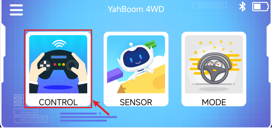
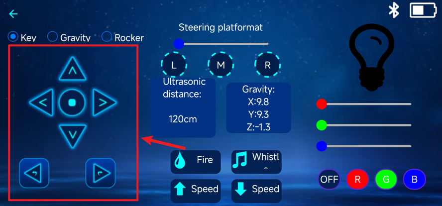
Connect the car, burn the program to MSPM0, put the car on the ground and plug in the power supply. Open the app, select the 4WD model, and after connecting to Bluetooth, you can control the car to move forward and backward, turn left and right, and rotate left and right through the app.

APP download: http://www.yahboom.net/software/app

Specific operation steps of YahboomRobot APP

① Download the corresponding App
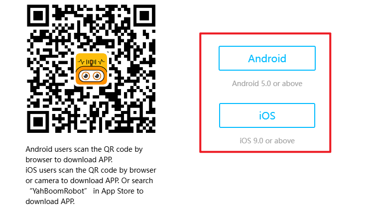
image-20250402122344638

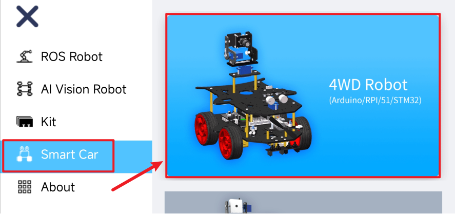
② Open the App and select 4WD Robot

image-20250402122915362

③ Open the Bluetooth interface and enable location permissions, etc.
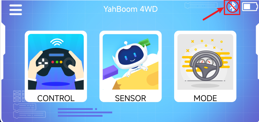
image-20250402122954206

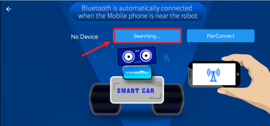
④Search for Bluetooth

image-20250402123019852

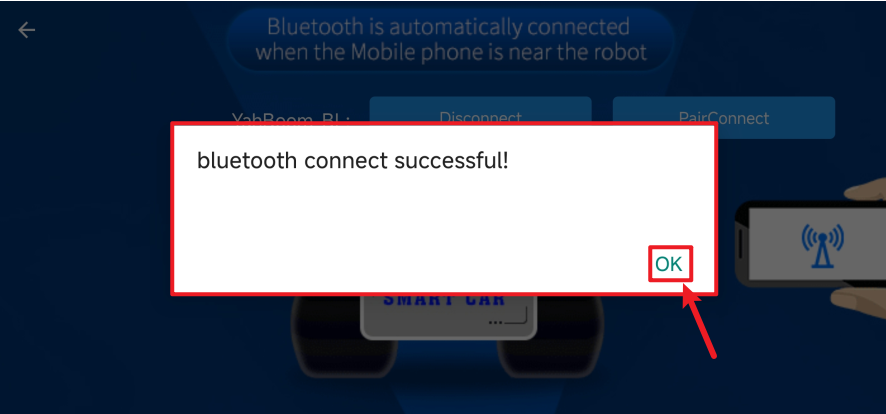
⑤Connect Bluetooth

image-20250402123052746

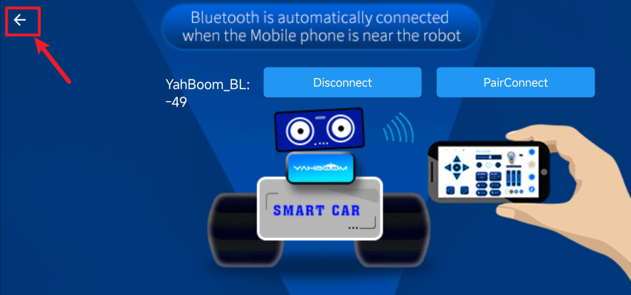
⑥Return to function selection page

image-20250402123110367

⑦Control interface

image-20250402140239098

⑧Areas supporting function control

image-20250402140320177

Servo ultrasonic avoid
K210-Automatic Driving

COMPANY

  • About us
  • Team Style
  • Blog

LEARNING & EXPLORATION

  • Tutorials
  • Edge AI hardware
  • Educational robots
  • Embedded intelligent hardware

WHERE TO BUY

  • Yahboom Online Store
  • Amazon
  • Alibaba
  • AliExpress
  • Mercado

TECHNOLOGY SUPPORT

  • Email: support@yahboom.com

BE A DISTRIBUTOR

  • Email: sales@yahboom.com
QR Code

Copyright © 2017-2026 Yahboom. All Rights Reserved.

EN/中文