Welcome to Wheeled Chassis Kit repository
05.Electric PTZ control
Electric PTZ control
Electric PTZ control1. Opening Notes2. Experimental PreparationThe relationship between the 4 motor interfaces and the car is as follows:Hardware wiring:Overall wiringWiring pins3. Key code analysis4. Experimental phenomenon
1. Opening Notes
Please read the "Introduction to Motors and Usage" in the information of the four-way motor driver board first to understand the motor parameters, wiring methods, and power supply voltage you are currently using. To avoid burning the motherboard or motor.
Motor: The case and code take the 310 motor of our store as an example.
2. Experimental Preparation
National Race Chassis V2 Four-wheel Drive Version, 4*310 Motors, 7.4V Lithium Battery, SG90 Digital Servo (4.8V-6.0V), Ultrasonic Module, STM32F103C8T6 Core Board.
The relationship between the 4 motor interfaces and the car is as follows:
M1 -> upper left motor (left front wheel of the car)
M2 -> lower left motor (left rear wheel of the car)
M3 -> upper right motor (right front wheel of the car)
M4 -> lower right motor (right rear wheel of the car)
Hardware wiring:
Overall wiring
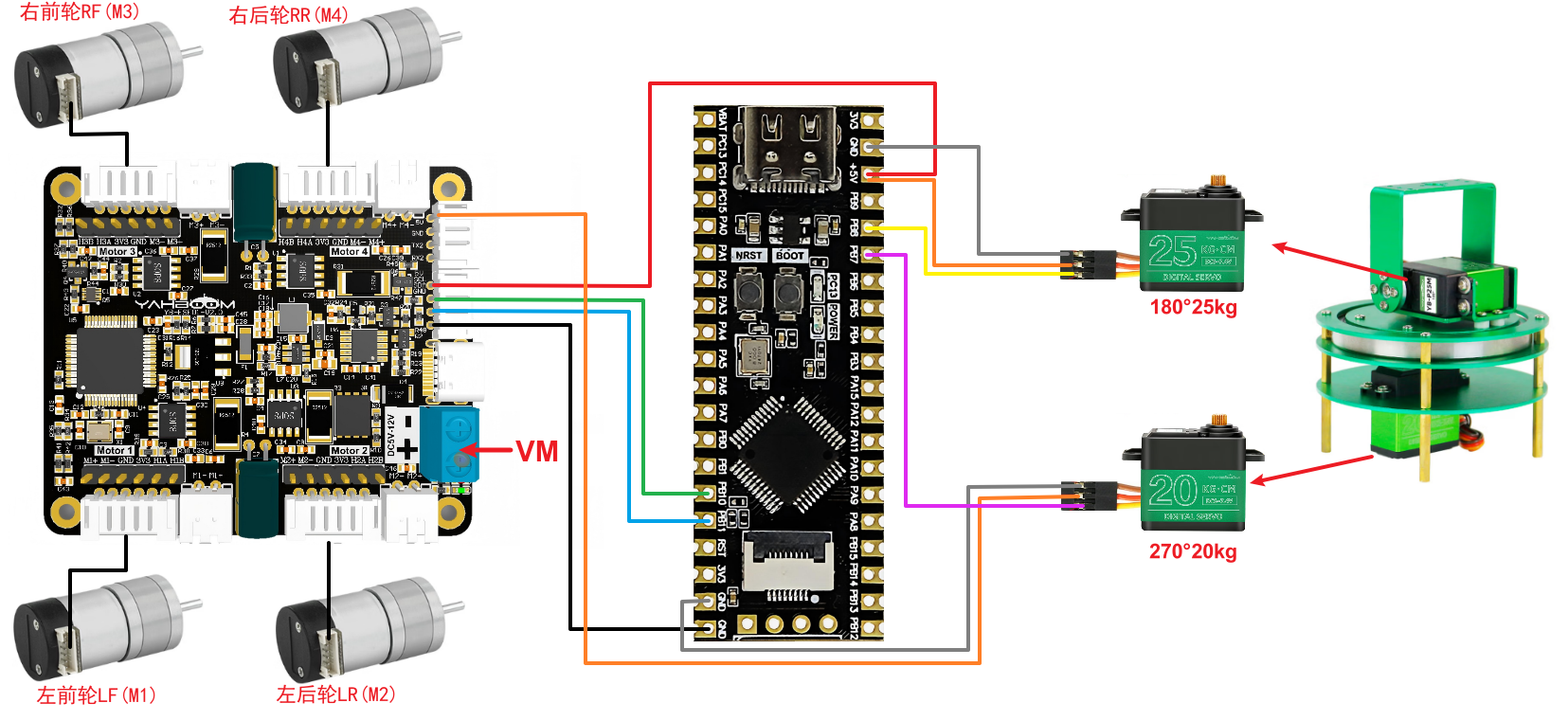
Wiring pins
| Four-way motor driver board | STM32C8T6 |
|---|---|
| 5V | 5V |
| GND | GND |
| SCL | PB10 |
| SDA | PB11 |
Take M1 motor as an example below, and other motors are similar.
| Motor | Four-way motor driver board (Motor1) |
|---|---|
| M2 | M1- |
| VCC | 3V3 |
| A | H1A |
| B | H1B |
| GND | GND |
| M1 | M1+ |
| 180° servo | STM32C8T6 |
|---|---|
| VCC | 5V |
| GND | GND |
| SIG | PB8 |
| 270° servo | STM32C8T6 |
|---|---|
| VCC | 5V |
| GND | GND |
| SIG | PB9 |
3. Key code analysis
bsp_motor_iic.c
x//配置电机 Configure the motorvoid Set_motor_type(uint8_t data){ i2cWrite(Motor_model_ADDR,MOTOR_TYPE_REG,2,&data);}
//配置死区 Configuring Dead Zonevoid Set_motor_deadzone(uint16_t data){ static uint8_t buf_tempzone[2]; buf_tempzone[0] = (data>>8)&0xff; buf_tempzone[1] = data; i2cWrite(Motor_model_ADDR,MOTOR_DeadZONE_REG,2,buf_tempzone);}
//配置磁环线 Configuring magnetic loopvoid Set_Pluse_line(uint16_t data){ static uint8_t buf_templine[2]; buf_templine[0] = (data>>8)&0xff; buf_templine[1] = data; i2cWrite(Motor_model_ADDR,MOTOR_PluseLine_REG,2,buf_templine);}
//配置减速比 Configure the reduction ratiovoid Set_Pluse_Phase(uint16_t data){ static uint8_t buf_tempPhase[2]; buf_tempPhase[0] = (data>>8)&0xff; buf_tempPhase[1] = data; i2cWrite(Motor_model_ADDR,MOTOR_PlusePhase_REG,2,buf_tempPhase);}
//配置直径 Configuration Diametervoid Set_Wheel_dis(float data){ static uint8_t bytes[4]; float_to_bytes(data,bytes); i2cWrite(Motor_model_ADDR,WHEEL_DIA_REG,4,bytes);}
//只能控制带编码器类型的电机 Can only control motors with encoders//传入参数:4个电机的速度 Input parameters: speed of 4 motorsvoid control_speed(int16_t m1,int16_t m2 ,int16_t m3,int16_t m4){ static uint8_t speed[8]; speed[0] = (m1>>8)&0xff; speed[1] = (m1)&0xff; speed[2] = (m2>>8)&0xff; speed[3] = (m2)&0xff; speed[4] = (m3>>8)&0xff; speed[5] = (m3)&0xff; speed[6] = (m4>>8)&0xff; speed[7] = (m4)&0xff; i2cWrite(Motor_model_ADDR,SPEED_Control_REG,8,speed);
}Define the function of writing configuration parameters to the four-way motor driver board and the motor control function, which are used to set key parameters such as motor type, dead zone, number of magnetic ring lines, reduction ratio and wheel diameter, and control the speed of the four motors.
main.c
xxxxxxxxxx
//1:520电机 2:310电机 3:测速码盘TT电机 4:TT直流减速电机 5:L型520电机 //1:520 motor 2:310 motor 3:speed code disc TT motor 4:TT DC reduction motor 5:L type 520 motor
int Angle_J1 = 0;//PB9 270°int Angle_J2 = 0;//PB8 180°
int main(void){ bsp_init(); ... Set_motor_type(2);//配置电机类型 Configure motor type delay_ms(100); Set_Pluse_Phase(20);//配置减速比 查电机手册得出 Configure the reduction ratio. Check the motor manual to find out delay_ms(100); Set_Pluse_line(13);//配置磁环线 查电机手册得出 Configure the magnetic ring wire. Check the motor manual to get the result. delay_ms(100); Set_Wheel_dis(48.00);//配置轮子直径,测量得出 Configure the wheel diameter and measure it delay_ms(100); Set_motor_deadzone(1600);//配置电机死区,实验得出 Configure the motor dead zone, and the experiment shows delay_ms(100); ...
/*现象:两个舵机都先归中,然后小车前进两秒后停下。接着两个舵机分别转动,最后归中。*/ /*Phenomenon: Both servos are centered first, then the cart moves forward for two seconds and stops. Then both servos rotate separately and finally return to the center.*/ Angle_J1 = 115;//270°舵机 delay_ms(100); Angle_J2 = 90; //180°舵机 delay_ms(1000); control_speed(300,300,300,300); delay_ms(2000); control_speed(0,0,0,0);
Angle_J1 = 60; delay_ms(1500); Angle_J1 = 250; delay_ms(1500); Angle_J2 = 0; delay_ms(1500); Angle_J2 = 170; delay_ms(1500); Angle_J1 = 115; delay_ms(100); Angle_J2 = 90;
while (1) { } }MOTOR_TYPE: used to set the type of motor used. Modify the corresponding number according to the comments based on the motor you are currently using.
After initializing the system, use Set_motor_type() and other functions to set the motor type and parameters according to MOTOR_TYPE. Then, Angle_J1 and Angle_J2 control the movement of the servo respectively, and control_speed() controls the movement of the car.
4. Experimental phenomenon
After connecting the car and burning the program to STM32, put the car on the ground, connect the power supply, return the servo to the center, the car moves forward for two seconds and then stops, the servo then turns to 60° and 250° respectively, and finally returns to the center.