Welcome to Wheeled Chassis Kit repository
07.Servo ultrasonic avoid
Servo ultrasonic avoid
Servo ultrasonic avoid1. Opening Notes2. Experimental PreparationThe relationship between the 4 motor interfaces and the car is as follows:Hardware wiring:Overall wiringSingle moduleYabo Ultrasonic PTZWiring pins3. Key code analysis4. Experimental phenomenon
1. Opening Notes
Please read the "Introduction to Motors and Usage" in the information of the four-way motor driver board first to understand the motor parameters, wiring methods, and power supply voltage you are currently using. To avoid burning the motherboard or motor.
Motor: The case and code take the 310 motor of our store as an example.
2. Experimental Preparation
Guosai chassis V2 four-wheel drive version, 4*310 motors, 7.4V lithium battery, SG90 digital servo (4.8V-6.0V), ultrasonic ranging module (HC-SR04), STM32F103C8T6 core board.
The relationship between the 4 motor interfaces and the car is as follows:
M1 -> upper left motor (left front wheel of the car)
M2 -> lower left motor (left rear wheel of the car)
M3 -> upper right motor (right front wheel of the car)
M4 -> lower right motor (right rear wheel of the car)
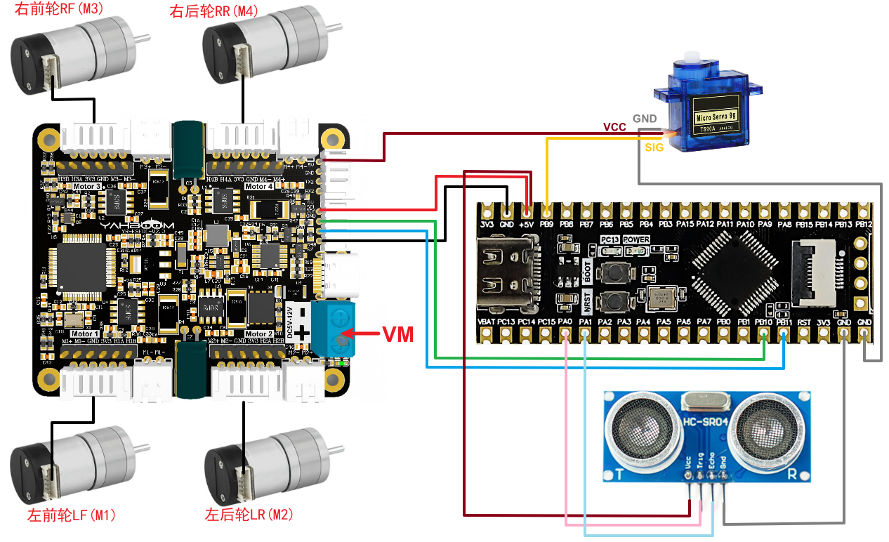
Hardware wiring:
Overall wiring
Single module
Yabo Ultrasonic PTZ
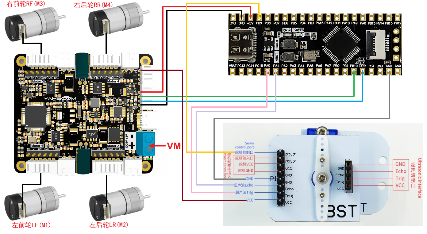
Wiring pins
| Four-way motor driver board | STM32C8T6 |
|---|---|
| 5V | 5V |
| GND | GND |
| SCL | PB10 |
| SDA | PB11 |
Take M1 motor as an example below, and other motors are similar
| Motor | Four-way motor driver board (Motor1) |
|---|---|
| M2 | M1- |
| VCC | 3V3 |
| A | H1A |
| B | H1B |
| GND | GND |
| M1 | M1+ |
| Ultrasonic ranging module (HC-SR04) | STM32C8T6 |
|---|---|
| VCC | 5V |
| GND | GND |
| ECHO | PA1 |
| TRIG | PA0 |
| Servo | STM32C8T6 |
|---|---|
| VCC | 5V |
| GND | GND |
| SIG | PB9 |
3. Key code analysis
bsp_motor_iic.c
x//配置电机 Configure the motorvoid Set_motor_type(uint8_t data){ i2cWrite(Motor_model_ADDR,MOTOR_TYPE_REG,2,&data);}
//配置死区 Configuring Dead Zonevoid Set_motor_deadzone(uint16_t data){ static uint8_t buf_tempzone[2]; buf_tempzone[0] = (data>>8)&0xff; buf_tempzone[1] = data; i2cWrite(Motor_model_ADDR,MOTOR_DeadZONE_REG,2,buf_tempzone);}
//配置磁环线 Configuring magnetic loopvoid Set_Pluse_line(uint16_t data){ static uint8_t buf_templine[2]; buf_templine[0] = (data>>8)&0xff; buf_templine[1] = data; i2cWrite(Motor_model_ADDR,MOTOR_PluseLine_REG,2,buf_templine);}
//配置减速比 Configure the reduction ratiovoid Set_Pluse_Phase(uint16_t data){ static uint8_t buf_tempPhase[2]; buf_tempPhase[0] = (data>>8)&0xff; buf_tempPhase[1] = data; i2cWrite(Motor_model_ADDR,MOTOR_PlusePhase_REG,2,buf_tempPhase);}
//配置直径 Configuration Diametervoid Set_Wheel_dis(float data){ static uint8_t bytes[4]; float_to_bytes(data,bytes); i2cWrite(Motor_model_ADDR,WHEEL_DIA_REG,4,bytes);}
...
//控制带编码器类型的电机 Control the motor with encoder type//传入参数:4个电机的pwm PWM of 4 motors//此函数可以结合实时编码器的数据,来实现control_speed的功能 This function can combine the data of real-time encoder to realize the function of control_speedvoid control_pwm(int16_t m1,int16_t m2 ,int16_t m3,int16_t m4){ static uint8_t pwm[8]; pwm[0] = (m1>>8)&0xff; pwm[1] = (m1)&0xff; pwm[2] = (m2>>8)&0xff; pwm[3] = (m2)&0xff; pwm[4] = (m3>>8)&0xff; pwm[5] = (m3)&0xff; pwm[6] = (m4>>8)&0xff; pwm[7] = (m4)&0xff; i2cWrite(Motor_model_ADDR,PWM_Control_REG,8,pwm);
}Define functions for writing configuration parameters to the four-way motor driver board and motor control functions to set key parameters such as motor type, dead zone, number of magnetic ring lines, reduction ratio, and wheel diameter, and control four motors. Send PWM signals to the motor driver board through i2c communication to adjust the speed and direction of the motor.
servo.c
xxxxxxxxxxvoid PWM_SetAngle(uint16_t angle) { // 角度范围限制 Angle range limitation if(angle > 180) angle = 180; // 角度转CCR值(0.5ms-2.5ms脉宽对应0-180度) Angle to CCR value (0.5ms-2.5ms pulse width corresponds to 0-180 degrees) uint16_t ccr = (uint16_t)(500 + angle * (2000.0 / 180.0)); TIM_SetCompare4(TIM4, ccr);}The PWM_SetAngle function is used to set the rotation angle of the servo. It controls the rotation position of the servo by adjusting the pulse width of the PWM (pulse width modulation) signal.
bsp_ultrasonic.c
xxxxxxxxxx//获取超声波的距离//Distance to obtain ultrasonic wavesu16 TIM2CH2_CAPTURE_STA,TIM2CH2_CAPTURE_VAL;void Get_Distane(void)        {        uint32_t sum = 0;    uint8_t valid_samples = 0;  // 有效测量次数计数器    Valid measurement count counter    uint32_t distance = 0;    for (int i = 0; i < 5; i++) {             TRIG_SIG = 1;              delay_us(15);       TRIG_SIG = 0;       if(TIM2CH2_CAPTURE_STA&0X80)//成功捕获到了一次高电平 //Successfully captured a high level once     {         distance=TIM2CH2_CAPTURE_STA&0X3F;          distance*=65536;                           //溢出时间总和 Overflow time sum         distance+=TIM2CH2_CAPTURE_VAL;     //得到总的高电平时间 Get the total high level time         distance=distance*170/1000;      //时间*声速/2(来回) 一个计数0.001ms  Time * speed of sound/2 (round trip), one count 0.001ms         // 过滤异常值(范围:20mm~4000mm)   Filter outliers (range: 20mm~4000mm)        if (distance >= 20 && distance <= 4000) {            sum += distance;            valid_samples++;        }         TIM2CH2_CAPTURE_STA=0;         //开启下一次捕获 Start the next capture     }     delay_ms(10);  // 测量间隔,防止信号干扰  Measurement interval to prevent signal interference }    // 计算平均值    Calculate the average    if (valid_samples > 0) {        g_distance = sum / valid_samples;  // 取有效样本的平均值 Take the average of the valid samples    } else {        g_distance = 0;  // 无有效数据时返回0   Returns 0 if there is no valid data    }}
...
void Ultrasonic_servo_mode(void){    int Len = 0;    int LeftDistance = 0, RightDistance = 0;    Get_Distane();    Len = g_distance;//  printf("Len=%d\r\n",Len);
    if(Len <= 150)//当遇到障碍物时  When encountering obstacles    {        control_pwm(0,0,0,0);//停下来做测距   Stop to measure distance                PWM_SetAngle(180);      // 左边   left        delay_ms(1500); //等待舵机到位    Waiting for the servo to arrive        Get_Distane();        LeftDistance = g_distance;//        printf("L:%d\r\n", LeftDistance);             PWM_SetAngle(0);        // 右边   right        delay_ms(1500); //等待舵机到位    Waiting for the servo to arrive        Get_Distane();        RightDistance = g_distance;//        printf("R:%d\r\n",RightDistance);                PWM_SetAngle(90);       //归位    Home        delay_ms(500); //等待舵机到位 Waiting for the servo to arrive
        if((LeftDistance < 130 ) &&( RightDistance < 130 ))//当左右两侧均有障碍物靠得比较近  When there are obstacles on both sides,        {            control_speed(-300,-300,300,300);//旋转掉头  Rotate U-turn            delay_ms(1000); //等待舵机到位 Waiting for the servo to arrive            delay_ms(1000);//            printf("Turn Around");        }        else if(LeftDistance >= RightDistance)//左边比右边空旷 The left side is more spacious than the right side        {                  control_speed(-200,-200,200,200);//左转    Turn left            delay_ms(1000); //等待舵机到位 Waiting for the servo to arrive            delay_ms(1000);//            printf("Left");        }        else//右边比左边空旷   The right side is more spacious than the left side        {            control_speed(200,200,-200,-200); //右转   Turn right            delay_ms(1000); //等待舵机到位 Waiting for the servo to arrive            delay_ms(1000);//            printf("Right");        }    }            else if(Len > 150)    {        control_speed(100,100,100,100);      //无障碍物,直行     No obstacles, go straight    }}
This code obtains ultrasonic distance measurement data through Get_Distane and controls the car to avoid obstacles in Ultrasonic_servo_mode. When measuring distance, PWM_SetAngle rotates the servo to detect the left and right distance, and control_speed adjusts the direction of movement. When encountering an obstacle (Len ≤ 150), the car stops to measure the left and right space and decides to turn left, right or U-turn; when there is no obstacle (Len > 150), it continues to go straight.
main.c
xxxxxxxxxx
//1:520电机 2:310电机 3:测速码盘TT电机 4:TT直流减速电机 5:L型520电机 //1:520 motor 2:310 motor 3:speed code disc TT motor 4:TT DC reduction motor 5:L type 520 motor
int main(void){ bsp_init(); ... Set_motor_type(2);//配置电机类型 Configure motor type delay_ms(100); Set_Pluse_Phase(20);//配置减速比 查电机手册得出 Configure the reduction ratio. Check the motor manual to find out delay_ms(100); Set_Pluse_line(13);//配置磁环线 查电机手册得出 Configure the magnetic ring wire. Check the motor manual to get the result. delay_ms(100); Set_Wheel_dis(48.00);//配置轮子直径,测量得出 Configure the wheel diameter and measure it delay_ms(100); Set_motor_deadzone(1300);//配置电机死区,实验得出 Configure the motor dead zone, and the experiment shows delay_ms(100); ... PWM_SetAngle(90); delay_ms(1000); printf("start\r\n"); while(1) { Ultrasonic_servo_mode();// delay_ms(100); }}MOTOR_TYPE: used to set the type of motor used. Modify the corresponding number according to the comments based on the motor you are currently using.
After initializing the system, use Set_motor_type() and other functions to set the motor type and parameters according to MOTOR_TYPE. Then, use PWM_SetAngle(90) to return the servo to its position. In the main loop, call Data_Analyse() to continuously parse the data received by the serial port, and call Ultrasonic_servo_mode() to implement ultrasonic obstacle avoidance control.
4. Experimental phenomenon
After connecting the car and burning the program to STM32, put the car on the ground, confirm that the servo pan/tilt is facing forward at 90 degrees, connect the power supply, and the car will automatically drive forward. When encountering an obstacle in front, the car's servo will turn left, then right, and measure the distance respectively. If the distance on the left is greater than the distance on the right, the car will turn left, otherwise it will turn right; thus avoiding the obstacle in front. (Note: Ultrasonic waves can only measure the distance perpendicular to (directly in front of) the ultrasonic wave)