Welcome to Wheeled Chassis Kit repository
02.4-channel tracking
Car line patrol based on four-way line patrol module
Car line patrol based on four-way line patrol module1. Introduction2. Experimental preparationThe relationship between the 4 motor interfaces and the car is as follows:Hardware wiring:Wiring using MSPM0 robot expansion boardWiring using MSPM0G3507 core board (Yahboom)Wiring pins3. Key code analysis4. Experimental phenomenon
1. Introduction
Please read the "Motor Introduction and Usage" in the four-way motor driver board information first to understand the motor parameters, wiring method, and power supply voltage you are currently using. To avoid burning the motherboard or motor.
2. Experimental preparation
National race chassis V2 four-wheel drive version, 4*310 motor, 7.4V lithium battery, four-way line patrol module, MSPM0 robot expansion board (optional), MSPM0G3507 core board (Yahboom).
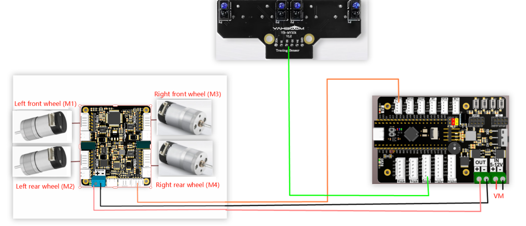
The relationship between the 4 motor interfaces and the car is as follows:
M1 -> upper left motor (left front wheel of the car)
M2 -> lower left motor (left rear wheel of the car)
M3 -> upper right motor (right front wheel of the car)
M4 -> lower right motor (right rear wheel of the car)
Hardware wiring:
Wiring using MSPM0 robot expansion board
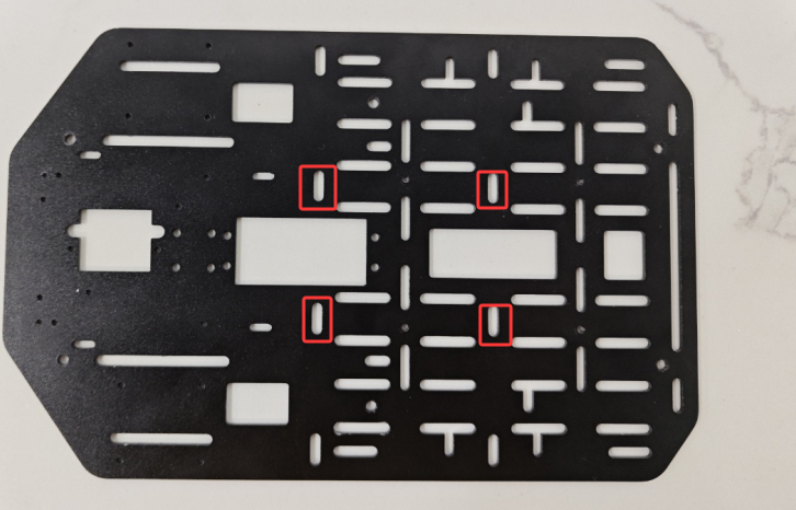
During the installation and wiring process, if the wiring length is not enough, you can move the MSPM0 robot expansion board forward a little and install it, as shown in the following figure.
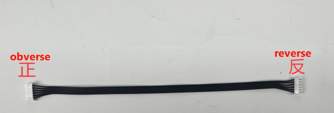
Note: The wire used for the four-way patrol module is: XH2.54 cable (6pin double-headed-all black-reverse 25cm), and the direction of the reverse cable holder is as shown in the following figure
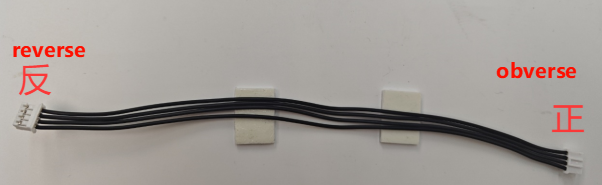
Note: The wire used to connect the MSPM0 robot expansion board to the four-way motor drive module is: XPH2.0-4pin cable, double-headed all black, reverse (200mm), and the direction of the reverse cable holder is as shown in the following figure
Wiring using MSPM0G3507 core board (Yahboom)
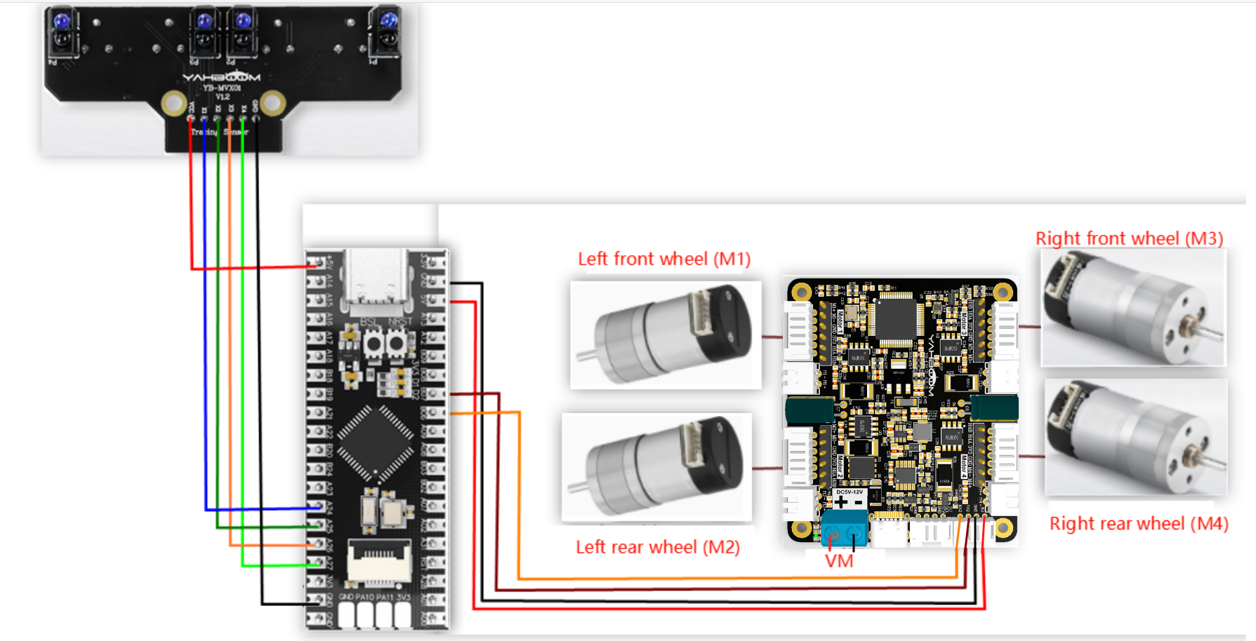
Wiring pins
| Four-way motor driver board | MSPM0G3507 core board (Yahboom) |
|---|---|
| RX2 | PB6 |
| TX2 | PB7 |
| GND | GND |
| 5V | 5V |
Take M1 motor as an example below, and other motors are similar
| Motor | Four-way motor driver board (Motor) |
|---|---|
| M2 | M1- |
| VCC | 3V3 |
| A | H1A |
| B | H1B |
| GND | GND |
| M1 | M1+ |
| Four-way line patrol module | MSPM0G3507 core board (Yahboom) |
|---|---|
| GND | GND |
| X4 | PA27 |
| X3 | PA26 |
| X2 | PA25 |
| X1 | PA24 |
| VCC | 5V |
3. Key code analysis
Four_linewalking.c
x
float APP_IR_PID_Calc(float actual_value){
float IRTrackTurn = 0; int8_t error; static int8_t error_last=0; static float IRTrack_Integral;//积分 Integral
error=actual_value; IRTrack_Integral +=error; //位置式pid Positional pid IRTrackTurn=error*IRTrack_Trun_KP +IRTrack_Trun_KI*IRTrack_Integral +(error - error_last)*IRTrack_Trun_KD; return IRTrackTurn;}
//获取X1X2X3X4的引脚电平 Get the pin levels of X1X2X3X4void Four_GetLineWalking(int *LineL1, int *LineL2, int *LineR1, int *LineR2){ *LineL1 = LineWalk_L1_IN; *LineL2 = LineWalk_L2_IN; *LineR1 = LineWalk_R1_IN; *LineR2 = LineWalk_R2_IN;}
void Four_LineWalking(void){ int LineL1 = 0, LineL2 = 0, LineR1 = 0, LineR2 = 0; Four_GetLineWalking(&LineL1, &LineL2, &LineR1, &LineR2);//获取黑线检测状态 Get black line detection status //debug// printf("L1:%d L2:%d R1:%d R2:%d\r\n",LineL1, LineL2, LineR1, LineR2);
// 0 0 X 0 // 1 0 X 0 // 0 1 X 0 //处理右锐角和右直角的转动 //Processing the right acute angle and the right right angle rotation if( (LineL1 == LOW || LineL2 == LOW) && LineR2 == LOW) { err=13; delay_ms(80); } // 0 X 0 0 // 0 X 0 1 // 0 X 1 0 //处理左锐角和左直角的转动 //Handling left acute angle and left right angle rotation else if ( LineL1 == LOW && (LineR1 == LOW || LineR2 == LOW)) { err=-13; delay_ms(80); } // 0 X X X //最左边检测到 //Most left detected else if( LineL1 == LOW ) { err=-9; delay_ms(10); } // X X X 0 //最右边检测到 //Most right detected else if ( LineR2 == LOW) { err=9;// Contrl_Speed(500,500,-500,-500); delay_ms(10); } // X 0 1 X //处理左小弯 //Processing of the left hand chicane else if (LineL2 == LOW && LineR1 == HIGH) //中间黑线上的传感器微调车左转 Sensor on the black line in the center fine tunes the car to turn left { err=-1; } // X 1 0 X //处理右小弯 //Processing of the right-hand chicane else if (LineL2 == HIGH && LineR1 == LOW) //中间黑线上的传感器微调车右转 The sensor on the center black line fine tunes the car to turn right { err=1; } // X 0 0 X //处理直线 //Processing straight lines else if(LineL2 == LOW && LineR1 == LOW) // 都是黑色, 加速前进 It's all black, so speed up. { err=0; } // 0 0 0 0 else if(LineL1 == LOW && LineL2 == LOW && LineR1 == LOW && LineR2 == LOW) // 都是黑色, 加速前进 It's all black, so speed up. { err = 0; } //当为1 1 1 1时小车保持上一个小车运行状态 //When it is 1 1 1 1 the trolley keeps the previous trolley in operation pid_output_IRR = (int)(APP_IR_PID_Calc(err)); Motion_Car_Control(IRR_SPEED, 0, pid_output_IRR); }
APP_IR_PID_Calc: Use PID algorithm to calculate. If the line patrol effect is not good, you can set KP and KD to 0 first, then slowly increase KP, and finally try to increase the value of KD
Four_GetLineWalking: Get the status of the four-way line patrol module sensor
Four_LineWalking: Adjust the driving state of the car by obtaining the status of the four-way line patrol module
app_motor_usart.c
xxxxxxxxxx//发送电机类型    Transmitter motor typevoid send_motor_type(motor_type_t data){    sprintf((char*)send_buff,"$mtype:%d#",data);    Send_Motor_ArrayU8(send_buff, strlen((char*)send_buff));    }
//发送电机死区    Send motor dead zonevoid send_motor_deadzone(uint16_t data){    sprintf((char*)send_buff,"$deadzone:%d#",data);    Send_Motor_ArrayU8(send_buff, strlen((char*)send_buff));}
//发送电机磁环脉冲  Send motor magnetic ring pulsevoid send_pulse_line(uint16_t data){    sprintf((char*)send_buff,"$mline:%d#",data);    Send_Motor_ArrayU8(send_buff, strlen((char*)send_buff));}
//发送电机减速比   Transmitting motor reduction ratiovoid send_pulse_phase(uint16_t data){    sprintf((char*)send_buff,"$mphase:%d#",data);    Send_Motor_ArrayU8(send_buff, strlen((char*)send_buff));}
//发送轮子直径    Send wheel diametervoid send_wheel_diameter(float data){    sprintf((char*)send_buff,"$wdiameter:%.3f#",data);    Send_Motor_ArrayU8(send_buff, strlen((char*)send_buff));}
Configure the motor parameters of the 4-way motor driver board
Contrl_Speed: Control the speed of the 4 motors separately
empty.c
xxxxxxxxxx//1:520电机 2:310电机 3:测速码盘TT电机 4:TT直流减速电机 5:L型520电机 //1:520 motor 2:310 motor 3:speed code disc TT motor 4:TT DC reduction motor 5:L type 520 motor
int main(void){ USART_Init(); printf("please wait..."); Set_Motor(MOTOR_TYPE); //修改电机PID,这里的参数是为四驱310底盘配置的,其他底盘需要自己测试修改 //Modify the motor PID, the parameters here are configured for the 4WD 310 chassis, other chassis need to test and modify their own! send_motor_PID(1.9,0.2,0.8); delay_ms(100);
while(1) { Four_LineWalking();//四路巡线,启动! Four-way line patrol, start! } }MOTOR_TYPE: used to set the type of motor used. Modify the corresponding number according to the comments based on the motor you are currently using.
USART_Init: Initialize the serial port for communicating with the four-way motor driver board
Set_Motor: Set the motor type
send_motor_PID: Set the motor PID
Four_LineWalking: Perform line walking with the car
app_motor.c
xxxxxxxxxxvoid Set_Motor(int MOTOR_TYPE){    if(MOTOR_TYPE == 1)    {        send_motor_type(1);//配置电机类型 Configure motor type        delay_ms(100);        send_pulse_phase(30);//配置减速比 查电机手册得出    Configure the reduction ratio. Check the motor manual to find out        delay_ms(100);        send_pulse_line(11);//配置磁环线 查电机手册得出 Configure the magnetic ring wire. Check the motor manual to get the result.        delay_ms(100);        send_wheel_diameter(67.00);//配置轮子直径,测量得出        Configure the wheel diameter and measure it        delay_ms(100);        send_motor_deadzone(1900);//配置电机死区,实验得出 Configure the motor dead zone, and the experiment shows        delay_ms(100);    }    else if(MOTOR_TYPE == 2)    {        send_motor_type(2);        delay_ms(100);        send_pulse_phase(20);        delay_ms(100);        send_pulse_line(13);        delay_ms(100);        send_wheel_diameter(48.00);        delay_ms(100);        send_motor_deadzone(1600);        delay_ms(100);    }    ...}
void Motion_Car_Control(int16_t V_x, int16_t V_y, int16_t V_z){    float robot_APB = Motion_Get_APB();    speed_lr = 0;    speed_fb = V_x;    speed_spin = (V_z / 1000.0f) * robot_APB;    if (V_x == 0 && V_y == 0 && V_z == 0)    {        Contrl_Speed(0,0,0,0);        return;    }
    speed_L1_setup = speed_fb + speed_spin;    speed_L2_setup = speed_fb + speed_spin;    speed_R1_setup = speed_fb  - speed_spin;    speed_R2_setup = speed_fb  - speed_spin;            if (speed_L1_setup > 1000) speed_L1_setup = 1000;    if (speed_L1_setup < -1000) speed_L1_setup = -1000;    if (speed_L2_setup > 1000) speed_L2_setup = 1000;    if (speed_L2_setup < -1000) speed_L2_setup = -1000;    if (speed_R1_setup > 1000) speed_R1_setup = 1000;    if (speed_R1_setup < -1000) speed_R1_setup = -1000;    if (speed_R2_setup > 1000) speed_R2_setup = 1000;    if (speed_R2_setup < -1000) speed_R2_setup = -1000;        //printf("%d\t,%d\t,%d\t,%d\r\n",speed_L1_setup,speed_L2_setup,speed_R1_setup,speed_R2_setup);        Contrl_Speed(speed_L1_setup, speed_L2_setup, speed_R1_setup, speed_R2_setup);        }
Set_Motor: This function is used to store the parameters of the motors sold in our store. By modifying the MOTOR_TYPE parameter at the beginning of empty.c, one-click configuration can be achieved. Under normal circumstances, do not modify the code here when using the motors of our store. If you use your own motors, you can select any motor and change the parameters to the parameters of the motor you use. If you do not understand the meaning of these parameters, you can check the document "4-way motor driver board control instructions" to understand the specific meaning of each instruction.
Motion_Car_Control: Control the movement of the car
4. Experimental phenomenon
Connect the car and burn the program to MSPM0, then place the car on the map with white background and black lines, and unplug the serial line that communicates with the four-way motor module. Adjust the four-way patrol module and adjust the module knob so that the module indicator light is on when encountering a black line, and the indicator light is off when it is not a black line. After the adjustment is completed, disconnect the power supply and plug the serial line back in. Put the car in the middle, let the two middle probes of the four-way patrol module be on the black line, then plug in the power supply, and the car will patrol the black line. The map adapted for this project is the high-difficulty map sold in this store, and it is adapted to the chassis of the four-wheel drive 310. If the patrol effect of other chassis is not good, you need to modify the motor PID and patrol PID in the code yourself.