Welcome to STM32-BoardCar repository
9. Basic timer (TIM6)
Basic timers
Basic timers1、software-hardware2、Brief principle2.1、Hardware schematic diagram2.2、Physical connection diagram2.3、Principle of control3、Engineering configuration3.1、Tips3.2、Pin configuration4、Main functions4.1、User function4.2、HAL library function parsing5、Experimental phenomenon
This tutorial demonstrates controlling the onboard LED1 and LED2 blinkers on the dev board using a basic timer (TIM6).
1、software-hardware
STM32F103CubeIDE
SSTM32 Robot Development Board
TIM: Chip internal peripherals
LED light: onboard
Type-C cable or ST-Link
Download or simulate the program of the development board
2、Brief principle
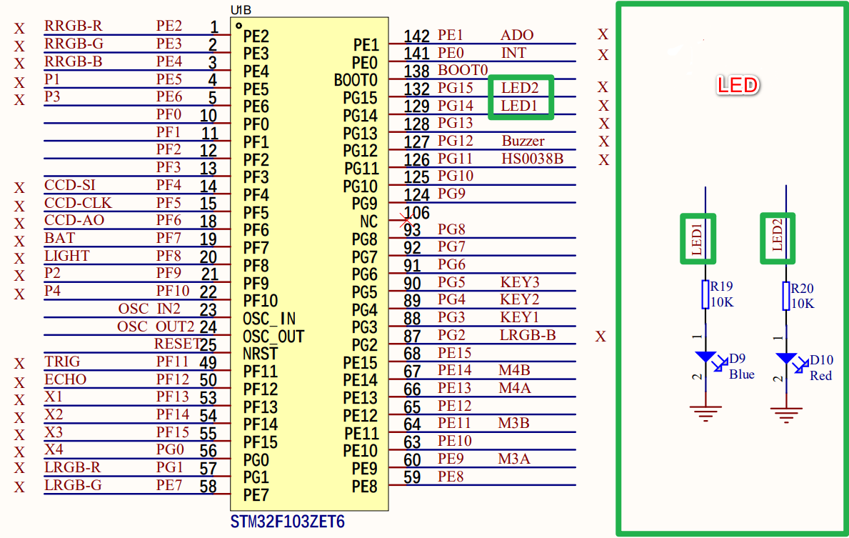
2.1、Hardware schematic diagram
2.2、Physical connection diagram

2.3、Principle of control
The GPIO output function is used to control the LED, and the timing function is realized through the basic timer.
GPIO output
By controlling the high and low level of the LED lamp pin to control the color of the LED lamp display.
LED:High level light, low level off
| LED(Schematic name) | Control pin | Functions |
|---|---|---|
| LED1 | PG14 | Control LED1 to turn on and off |
| LED2 | PG15 | Control LED2 to turn on and off |
Basic timers
The timing function of TIM6 on the STM32F103ZET6 development board was used
| Timer types | Basic timer |
|---|---|
| The name of timer | TIM6、TIM7 |
| Number of counter bits | 16 |
| Counting mode | incrementally |
| Predivision coefficient | 1-65536 |
| Generating DMA requests | Yes |
| Capture/compare channels | 0 |
| Complementary output | No |
| Clock frequency | 72MHz (Max) |
| Mount bus | APB1 |
Time base unit
| register | Funciton |
|---|---|
| The counter register(TIMx_CNT) | The current value of the counter |
| Predivision register(TIMx_PSC) | Set frequency division coefficient (1-65536) |
| Automatically reload registers(TIMx_ARR) | The counter counts the boundary and the overloaded value |
Timing formula
| parameters | Meaning |
|---|---|
| T(s) | Timing time in seconds |
| ARR | Automatically reload the value |
| PSC | Predivision coefficient |
| TIM_CLK | The timer ticks in Hz |
Timing time for the project: 10ms
3、Engineering configuration
Project Configuration: Prompts for configuration options in the STM32CubeIDE project configuration process
3.1、Tips
Omitted project configuration: New project, chip selection, project configuration, SYS for pin configuration, RCC configuration, clock configuration, and project configuration content
The project configuration part, which is not omitted, is the key point to configure in this tutorial.
xxxxxxxxxxPlease refer to [2. Development environment construction and use: STM32CubeIDE installation and use] to understand how to configure the omitted parts of the project.
3.2、Pin configuration
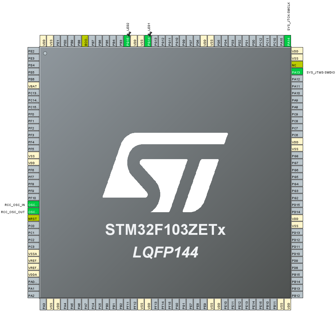
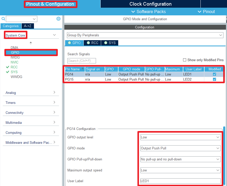
- Configure the specified pin function
You can directly select the corresponding pin number in the pin view, and the corresponding option will appear when the mouse is left clicked
- GPIO
- Timers

- NVIC

- Advanced Settings
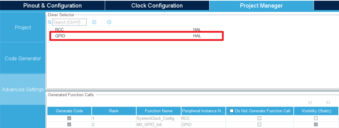
- Generating code

4、Main functions
This section mainly introduces the functional code written by users. Detailed code can be opened by yourself in the project file we provide, and enter the Bsp folder to view the source code.
4.1、User function
HAL_TIM_IRQHandler:The timer interrupt service function
| Function prototypes | void HAL_TIM_IRQHandler(TIM_HandleTypeDef *htim) |
|---|---|
| Functional Description | The timer interrupt service function |
| Input parameters | htim:Timer handle address |
| Return value | None |
| Notes | 1. Internally, the function needs to determine the interrupt type and clear the corresponding interrupt flag, and finally call the callback function Define the USE_HAL_IRQ macro to switch between different interrupt handling functions |
xxxxxxxxxx/*If the HAL library is used, the HAL_TIM_IRQHandler function is invoked to automatically handle timer interrupts.If the HAL library is not used, the timer update interrupt is checked to see if the interrupt bit is set.*/void TIM6_IRQHandler(void){#if USE_HAL_IRQHAL_TIM_IRQHandler(&htim6);//Using HAL_TIM_PeriodElapsedCallback is automatically invoked#elseif (__HAL_TIM_GET_FLAG(&htim6, TIM_FLAG_UPDATE) != RESET)//Check if the TIM update interrupt occurred{if (__HAL_TIM_GET_IT_SOURCE(&htim6, TIM_IT_UPDATE) != RESET) //Check if interrupts for TIM6 are enabled{__HAL_TIM_CLEAR_IT(&htim6, TIM_IT_UPDATE);//Clearing interruptsg_time++;if(g_time % 100 == 0)//1s = 100*10ms{g_time = 1;HAL_GPIO_TogglePin(LED1_GPIO_Port,LED1_Pin);}else if(g_time % 50 == 0)//500ms = 50*10ms{HAL_GPIO_TogglePin(LED2_GPIO_Port,LED2_Pin);}}}#endif}
HAL_TIM_PeriodElapsedCallback:The timer update interrupt callback function
| Function prototypes | void HAL_TIM_PeriodElapsedCallback(TIM_HandleTypeDef *htim) |
|---|---|
| Functional Description | The timer update interrupt callback function |
| Input parameters | htim:Timer handle address |
| Return value | None |
| Notes | This function is called by HAL_TIM_IRQHandler, which allows you to write specific tasks |
xxxxxxxxxx/*HAL library internal timer update interrupt callback function*/void HAL_TIM_PeriodElapsedCallback(TIM_HandleTypeDef *htim){if(htim->Instance==TIM6){g_time++;}if(g_time % 100 == 0)//1s = 100*10ms{g_time = 1;HAL_GPIO_TogglePin(LED1_GPIO_Port,LED1_Pin);}if(g_time % 50 == 0)//500ms = 50*10ms{HAL_GPIO_TogglePin(LED2_GPIO_Port,LED2_Pin);}}
4.2、HAL library function parsing
The HAL library functions that were covered in the previous tutorial will not be covered
xxxxxxxxxxIf you want to find the HAL library and LL library function analysis involved in the entire tutorial, you can view the documents in the folder [8. STM32 Manual: STM32F1_HAL Library and LL Library_User Manual]
function:HAL_TIM_Base_Init
| Function prototypes | HAL_StatusTypeDef HAL_TIM_Base_Init(TIM_HandleTypeDef *htim) |
|---|---|
| Functional Description | Initialize the timer base unit |
| Input parameters | htim:Timer handle address |
| Return value | HAL status value:HAL_OK、HAL_ERROR、HAL_BUSY、HAL_TIMEOUT |
| Notes | This calls the MCU low-level initialization function HAL_TIM_Base_MspInit to set the pins, clocks, and interrupts |
function:HAL_TIM_Base_MspInit
| Function prototype | void HAL_TIM_Base_MspInit(TIM_HandleTypeDef *htim); |
|---|---|
| Functional description | Initialize the peripheral clock, GPIO, and NVIC for the timer |
| Input parameters | htim:Timer handle address |
| Return value | None |
function:HAL_TIM_Base_MspDeInit
| Function prototype | void HAL_TIM_Base_MspDeInit(TIM_HandleTypeDef *htim) |
|---|---|
| Functional description | Uninitialize the timer peripheral clock, GPIO, and NVIC |
| Input parameters | htim:Timer handle address |
| Return value | None |
function:HAL_TIM_Base_Start_IT
| Function prototype | HAL_StatusTypeDef HAL_TIM_Base_Start_IT(TIM_HandleTypeDef *htim) |
|---|---|
| Functional description | Starts the timer and enables the interrupt function of the timer能 |
| Input parameters | htim:Timer handle address |
| Return value | HAL status value:HAL_OK、HAL_ERROR、HAL_BUSY、HAL_TIMEOUT |
| Notes | This function needs to be called by the user to enable and start the update interrupt of the timer |
5、Experimental phenomenon
After downloading the program successfully, press the RESET button of the development board to observe the phenomenon of the development board
xxxxxxxxxxFor program download, please refer to [2. Development environment construction and use: program download and simulation]
现象:
LED1:The bright-off time interval is 1 second
LED2:The bright-off time interval is 0.5 seconds
Experimental phenomena can be found in [Basic Timer_Experimental Phenomenon.mp4]