Welcome to STM32-BoardCar repository
18. USB communication
USB communication
USB communication1、software-hardware2、Brief principle2.1、Hardware schematic diagram2.2、Physical connection diagram2.3、Principle of control3、Engineering configuration3.1、Notes3.2、Pin configuration4、Main Function4.1、User function4.2、HAL library function parsing5、Experimental phenomenon
This tutorial demonstrates: using the USB Full Speed Device interface to simulate the serial port to send and receive data (OLED shows USB connection status, LED represents different connection status).
1、software-hardware
STM32F103CubeIDE
STM32 robot expansion board
USB: Chip internal peripheral
LED: Onboard
OLED: External
Type-C cable or ST-Link
Download or simulate the program of the development board
2、Brief principle
2.1、Hardware schematic diagram
The LED interface is not shown here, you can refer to the schematic diagram by yourself

2.2、Physical connection diagram
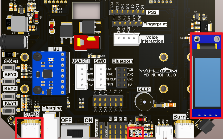
| OLED | STM32 board |
|---|---|
| VCC | VCC |
| SCL | SCL |
| SDA | SDA |
| GND | GND |
| STM32 USB | PC |
|---|---|
| Type-C interface | USB interface |
The Type-C data cable was used to connect the computer to the STM USB interface
2.3、Principle of control
- USB:(Universal Serial Bus)
| USB | Characteristics |
|---|---|
| Class of speed | Low speed(USB1.0:1.5Mbps) Full speed(USB1.1:12Mbps) High speed(USB2.0:480Mbps) Super high speed(USB3.0:5Gbps、USB3.1:10Gbps) The development board is in full speed mode |
| Communication interface | Development board uses 16-pin Type-C interface (see schematic) |
| Data transfer | Control transmission Interrupt transmission Bulk transfer Isochronous transmission |
| Advantages | 1. Support hotplugging and PNP (Plug-and-Play); 2. Provide USB peripherals with various speed levels to adapt to different requirements; 3. The port has very flexible expansibility; 4. Provides a single, easy-to-use standard connection type; 5. To meet the requirements of various types of peripheral devices, USB provides four different data transfer types. |
- USB Protocol
The USB bus uses differential signal transmission, where D+ and D- represent the positive and negative data lines of the differential signal respectively;
USB1.1 and USB2.0 use a differential signal level of 3.3V and USB3.0 uses a differential signal level of 5V.
xxxxxxxxxxUSB related knowledge can go to the "USB Encyclopedia of USB Chinese network" for understanding and learning, the following only introduces the common concepts
- Full speed/low speed USB bus device connection method
High speed/full speed equipment:D+ connected with 1.5k pull-up resistor;
Low speed equipment:D-connected 1.5k pull-up resistor;
- Bus status
| Level type | Scope |
|---|---|
| Difference 1 | D+>2.8V,D-<0.3V |
| Difference 0 | D+<0.3V,D-<0.3V |
| Single ended 0(SE0) | D+<0.3V,D-<0.3V |
| Single ended 1(SE1) | D+>2.8V,D->2.8V |
| J state: Low speed Full speed High speed | Difference 0 Difference 1 Difference 1 |
| K state Low speed Full speed High speed | Difference 1 Difference 0 Difference 0 |
| Restore status | K state |
| Packet start(SOF) | The USB data bus switches from the idle state to the K state |
| Packet end(EOP) | The SE0 lasts for two basic time units, and the J state lasts for one time unit |
- Encoding of USB signals
The data in USB is encoded by NRZI (none-return to zero inverted), and the different states of D+ and D- lines are defined as J and K.
Encoding/decoding of data (reverse non-return-to-zero code)

xxxxxxxxxxNote: The edge that meets 0 changes its state. If it is 1, the original state remainsBefore the data is NRZI encoded, a 0 signal is inserted after every six consecutive 1 signals so as not to lose synchronization.
- USB Protocol layer
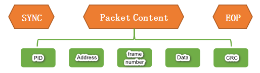
Packet is the basic unit of information transmission in USB system. All data is transmitted on the bus after being packaged.
Each packet consists of six parts: synchronization field (SYNC), packet identifier (PID), address field (ADDR), DATA field (including frame number), validation field (CRC), End of Packet (EOP).
- Practical Applications
The STM32F103ZET6 has an embedded device controller compatible with full speed USB, which complies with the standard for full speed USB devices (12 MBPS).
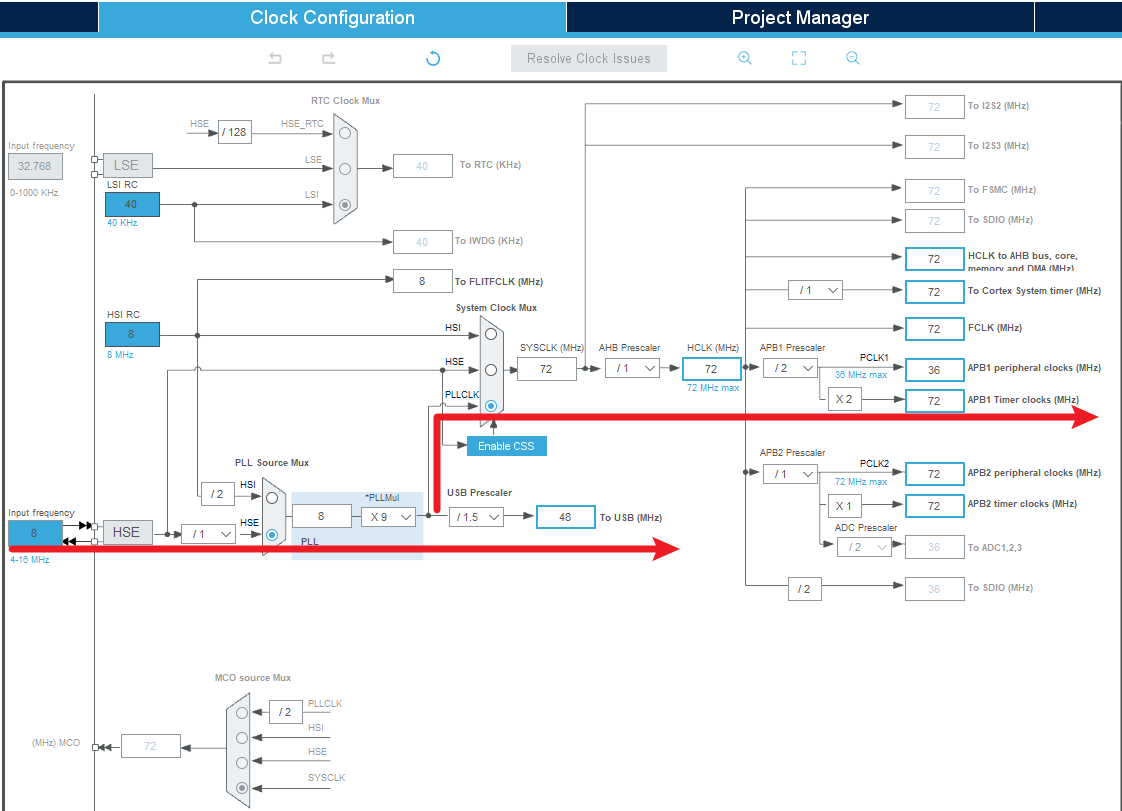
The USB-specific 48MHz clock is generated directly from the internal main PLL (the clock source must be a HSE crystal oscillator).
| source file | function |
|---|---|
| usb_device.c | USB device initialization function |
| usbd_conf.c | USB protocol parameters, GPIO initialization, and other functions |
| usbd_cdc_if.c | Virtual serial port receiving and sending functions |
| usbd_desc.c | USB descriptor and USB enumeration processing |
xxxxxxxxxxUSB related knowledge does not do too much introduction, you can consult the information on the Internet, mainly introduces the functions used in engineering
3、Engineering configuration
Project Configuration: Prompts for configuration options in the STM32CubeIDE project configuration process
3.1、Notes
Omitted project configuration: New project, chip selection, project configuration, SYS for pin configuration, RCC configuration, clock configuration, and project configuration content
The project configuration part, which is not omitted, is the key point to configure in this tutorial.
xxxxxxxxxxPlease refer to [2. Development environment construction and use: STM32CubeIDE installation and use] to understand how to configure the omitted parts of the project.
3.2、Pin configuration
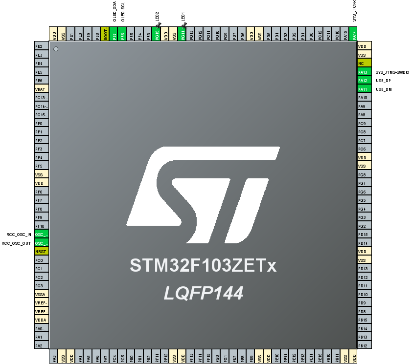
- Configure the specified pin function
You can directly select the corresponding pin number in the pin view, and the corresponding option will appear when the mouse is left clicked
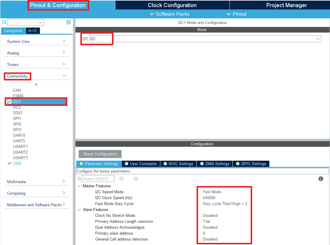
- I2C
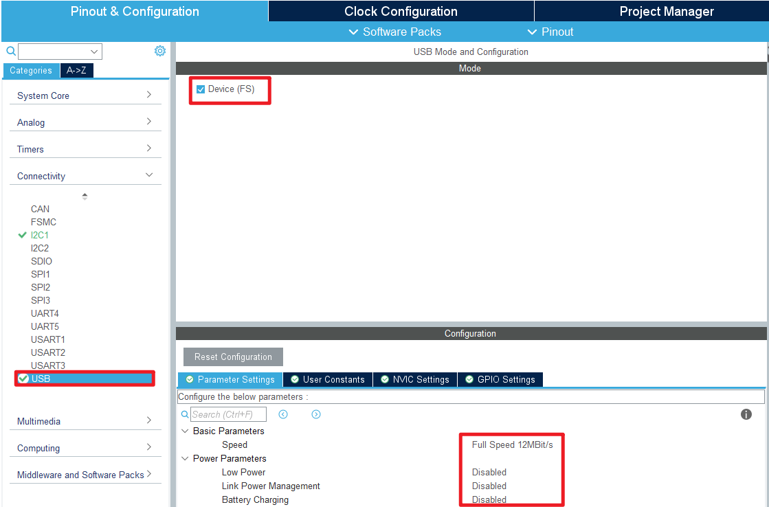
- USB
- Clock Configuration
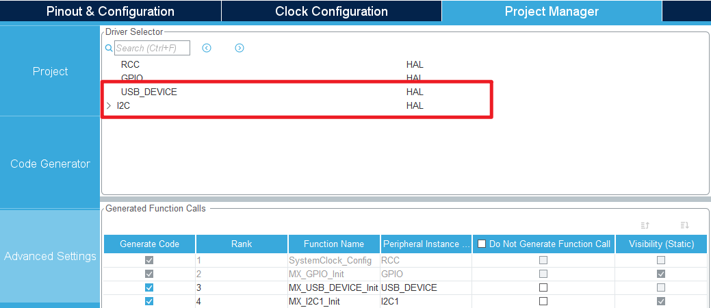
- Advanced Settings
- Generating code

4、Main Function
This section mainly introduces the functional code written by users. Detailed code can be opened by yourself in the project file we provide, and enter the Bsp folder to view the source code. .
4.1、User function
function:USB_Init
| Function prototypes | void USB_Init(void) |
|---|---|
| Functional Description | USB pin initialization |
| Input parameters | None |
| Return value | None |
| Tips | Prevent the need to plug and unplug the USB port again after downloading the program |
function:VCP_Status
| Function prototypes | void VCP_Status(void) |
|---|---|
| Functional Description | Check the USB connection status |
| Input parameters | None |
| Return value | None |
function:usb_printf
| Function prototypes | void usb_printf(const char *format, ...) |
|---|---|
| Functional Description | printf redefined to usb serial port (send function) |
| Input parameters | Specifies the content and format to output |
| Return value | None |
function:Deal_Recv
| Function prototypes | void Deal_Recv(void) |
|---|---|
| Functional Description | Process the received data |
| Input parameters | None |
| Return value | None |
| Tips | This routine prints the received data and displays the length of the data |
4.2、HAL library function parsing
The HAL library functions that were covered in the previous tutorial will not be covered
xxxxxxxxxxIf you want to find the HAL library and LL library function analysis involved in the entire tutorial, you can view the documents in the folder [8. STM32 Manual: STM32F1_HAL Library and LL Library_User Manual]
function:MX_USB_DEVICE_Init
| Function prototypes | void MX_USB_DEVICE_Init(void) |
|---|---|
| Functional Description | Initialize the USB device |
| Input parameters | None |
| Return value | None |
function:MX_USB_DEVICE_Init
| Function prototypes | USBD_StatusTypeDef USBD_Init (USBD_HandleTypeDef *pdev, USBD_DescriptorsTypeDef *pdesc, uint8_t id) |
|---|---|
| Functional Description | Initialize the configuration and parameters of the USB device |
| Input parameters1 | pdev:Handle to a USB device |
| Input parameters2 | pdesc:USB device descriptor information |
| Input parameters3 | id:The identifier of the USB device |
| Return value | USB status:USBD_OK、USBD_BUSY、USBD_FAIL |
function:USB_LP_CAN1_RX0_IRQHandler
| Function prototypes | void USB_LP_CAN1_RX0_IRQHandler(void) |
|---|---|
| Functional Description | Handle USB_LP_CAN1_RX0_IRQn interrupt (USB low priority and CAN1 receive 0 interrupt) |
| Input parameters | None |
| Return value | None |
5、Experimental phenomenon
After downloading the program successfully, press the RESET button of the development board to observe the OLED display and LED display
xxxxxxxxxxFor program download, please refer to [2. Development environment construction and use: program download and simulation]
phenomenon:
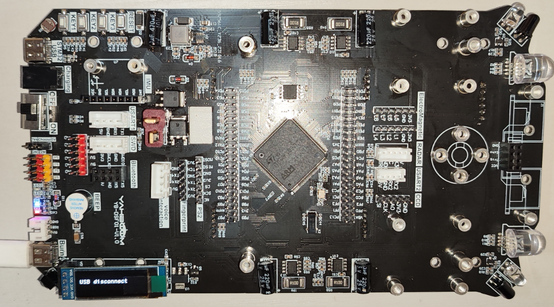
The STM32 USB interface is not connected:LED1 off, OLED display "USB disconnect";
Connect the STM32 USB port:LED1 bright, OLED display "USB connect";
Use the serial debugging assistant to connect the virtual serial port of the USB interface. Sending data will return the same data.
If the virtual serial port shows an exception in the Device Manager:Install "STM32 USB virtual serial port Driver" in the "Project Source" folder

Note the Type-C data line interface location for the following experimental phenomena