Welcome to STM32-BoardCar repository
6. Four-way tracking module
Four-way tracking module
Four-way tracking module1、software-hardware2、Brief principle2.1、Hardware schematic diagram2.2、Physical Connection Graph2.3、Principle of control3、Engineering configuration3.1、Notes3.2、Pin configuration4、Main FunctionUser function5、Experimental phenomenon
This tutorial demonstrates how to read the level of an external 4-way tracking module on your development board using the GPIO input function.
1、software-hardware
STM32F103CubeIDE
STM32 robot expansion board
A four-way tracking module is externally connected to the development board
Type-C cable or ST-Link
Download or simulate the program of the development board
2、Brief principle
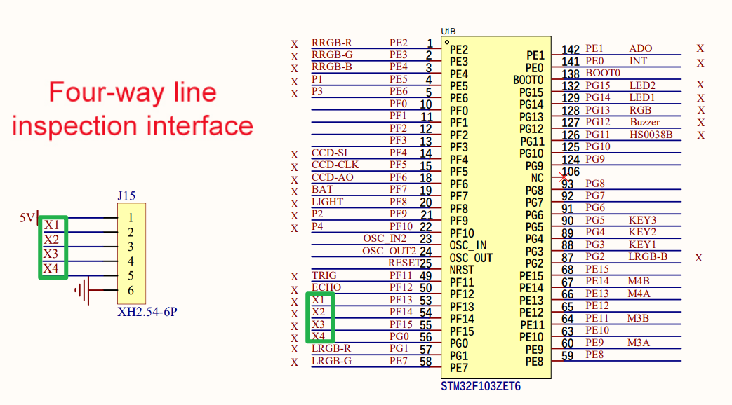
2.1、Hardware schematic diagram
2.2、Physical Connection Graph
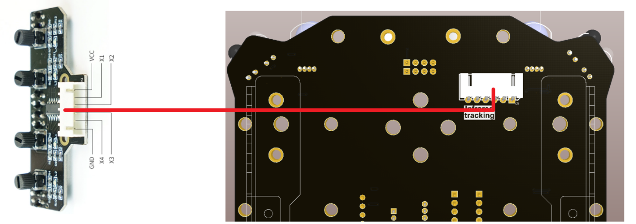
Use the 6Pin cable of XH2.54 and connect it to the corresponding interface
2.3、Principle of control
The interface levels of X1, X2, X3, X4 of the four-way tracking module are read to determine whether the black line is detected.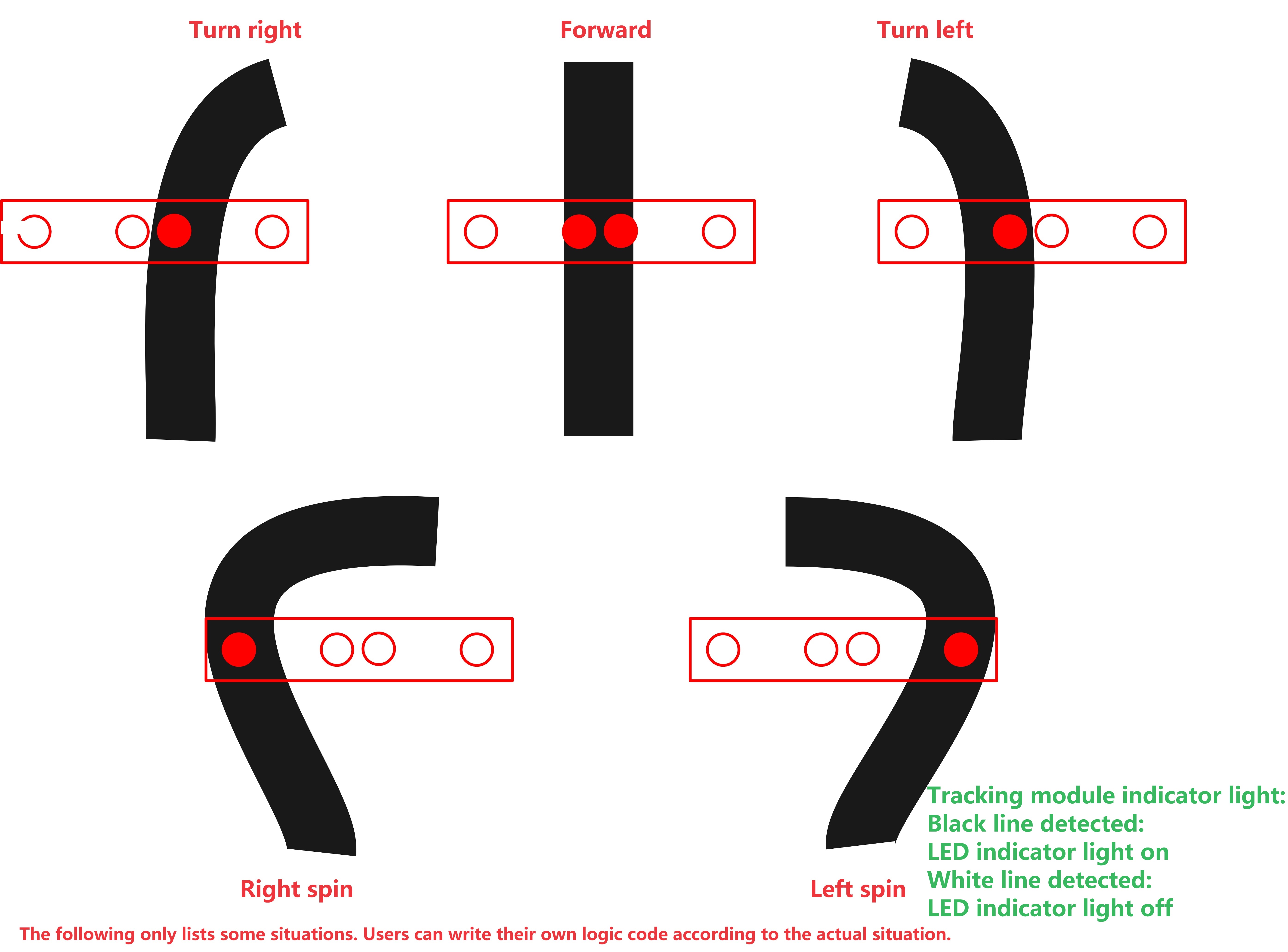
- Black line detected:The light is on, and the output level of the corresponding interface of the four-way inspection module is low
- White line detected:The light is off and the corresponding interface of the four-way inspection module outputs a high level
| RGB(Schematic name) | Control pin | feature |
|---|---|---|
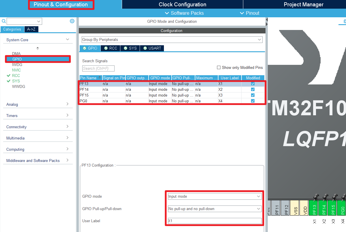
| X1 | PF13 | Read the level of the X1 interface |
| X2 | PF14 | Read the level of the X2 interface |
| X3 | PF15 | Read the level of the X3 interface |
| X4 | PG0 | Read the level of the X4interface |
xxxxxxxxxxNote: The corresponding relationship between interface, LED and adjustment knob is subject to the screen print number, for example: X1 corresponds to L1 and SW1
3、Engineering configuration
Project Configuration: Prompts for configuration options in the STM32CubeIDE project configuration process
3.1、Notes
Omitted project configuration: New project, chip selection, project configuration, SYS for pin configuration, RCC configuration, clock configuration, and project configuration content
The project configuration part, which is not omitted, is the key point to configure in this tutorial.
xxxxxxxxxxPlease refer to [2, development environment construction and use: STM32CubeIDE installation - Use] to understand how to configure the omitted part of the project
3.2、Pin configuration
- GPIO
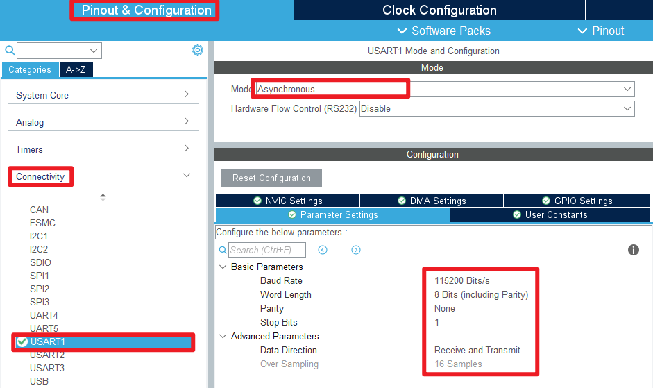
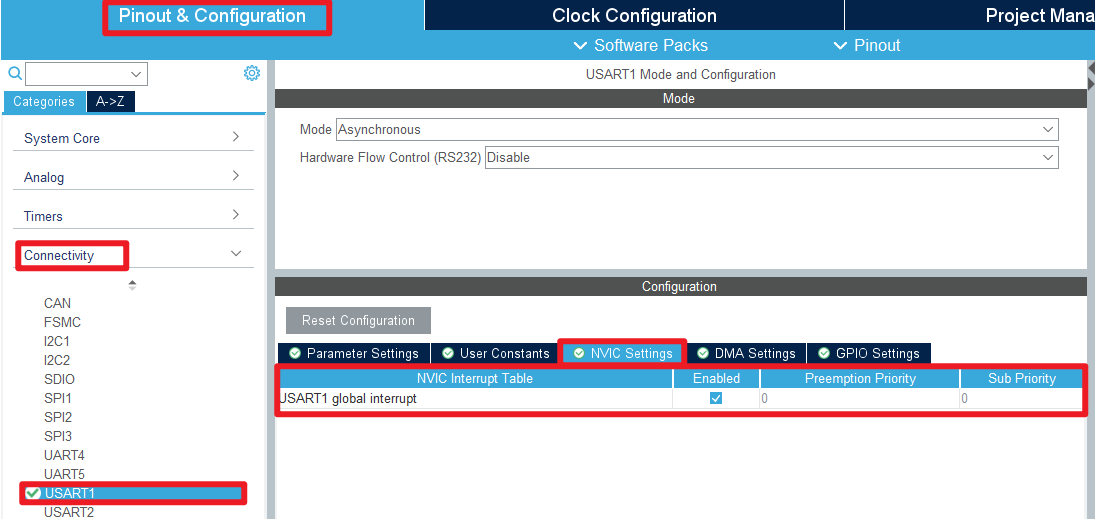
- USART1
- 生成代码

4、Main Function
This paper mainly introduces the functional code written by users. Detailed code can be opened by yourself in the project file we provide, and enter the Bsp folder to view the source code. .
User function
Many of the common HAL library functions were covered in Chapter 3, but they will not be covered here.
函数:Read_irtracking
| Function prototypes | uint8_t Read_irtracking(Irtracking_Pin irtracking) |
|---|---|
| Functional Description | Read the interface level of the four-way tracking module |
| Input parameters | irtracking:Four-way tracking module pin, X1, X2, X3, X4 |
| Return value | 0或1:0 is low, 1 is high |
5、Experimental phenomenon
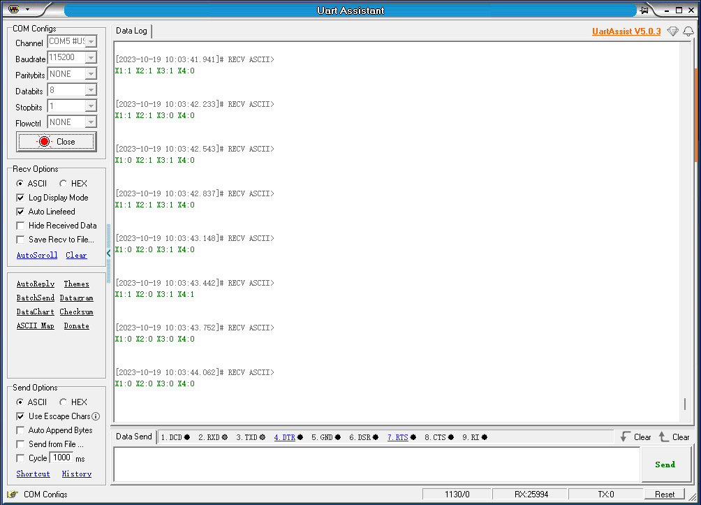
After downloading the program successfully, press the RESET button of the development board to open the serial debugging assistant to observe the phenomenon
xxxxxxxxxxProgram download can refer to [2, development environment construction and use: program download and simulation]
phenomenon:
The serial port prints the corresponding detection value of each tracking probe of the four-channel tracking module (0 represents low level, 1 represents high level).