Welcome to STM32-BoardCar repository
16. DMA:SPI
DMA:SPI
DMA:SPI1、software-hardware2、Brief principle2.1、Hardware schematic diagram2.2、Physical connection diagram2.3、Principle of control3、Engineering configuration3.1、Notes3.2、Pin configuration4、Main function4.1、User function4.2、HAL library function parsing5、Experimental phenomenon
This tutorial demonstrates: SPI (SPI2) communication via DMA
1、software-hardware
STM32F103CubeIDE
STM32 robot expansion board
USART, SPI, DMA: chip internal peripherals
Key, external Flash (W25Q64) : onboard
Type-C cable or ST-Link
Download or simulate the program of the development board
2、Brief principle
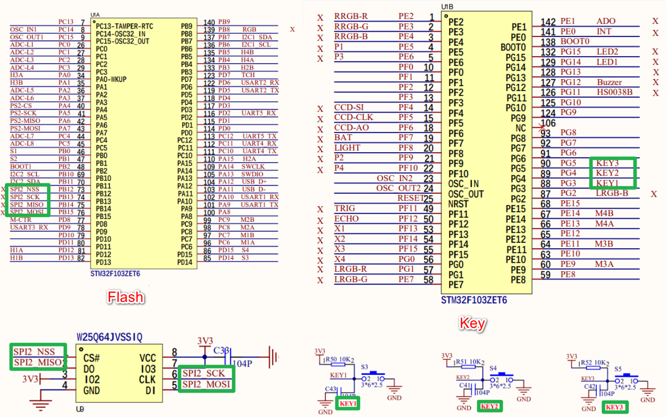
2.1、Hardware schematic diagram
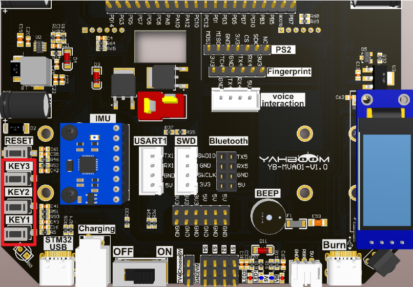
2.2、Physical connection diagram

2.3、Principle of control
- SPI
Using SPI2 to communicate with external Flash (W25Q64), SPI related knowledge will not be introduced, you can see the previous [Chapter 3:3.14 Off-chip Flash] tutorial
- DMA(Direct Memory Access)
STM32F103ZET6 has a total of two DMA controllers, DMA1 has 7 channels, DMA2 has 5 channels;
It is used for high-speed data transfer between peripheral equipment and memory and between memory and memory.
DMA features
The initialization and start of DMA are completed by the CPU, and the transfer process is executed by the DMA controller without the participation of the CPU, so that the CPU resources are saved to do other operations.
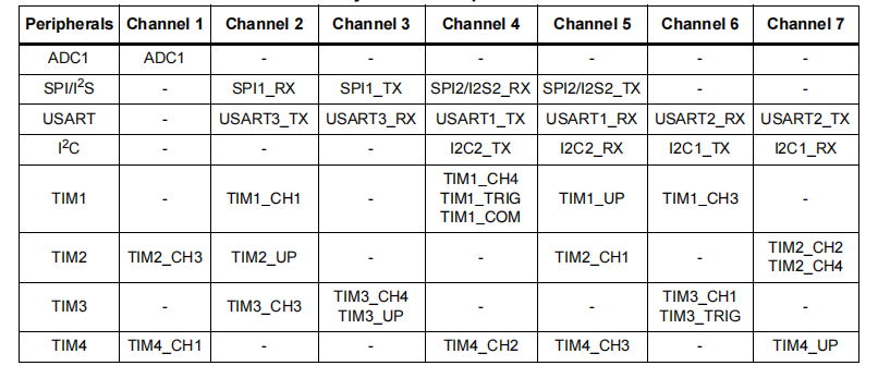
DMA1 requests per channel
DMA2 requests per channel
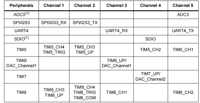
DMA1 channels 4 and 5 are used in this tutorial
3、Engineering configuration
Project Configuration: Prompts for configuration options in the STM32CubeIDE project configuration process
3.1、Notes
Omitted project configuration: New project, chip selection, project configuration, SYS for pin configuration, RCC configuration, clock configuration, and project configuration content
The project configuration part, which is not omitted, is the key point to configure in this tutorial.
Please refer to [2. Development environment construction and use: STM32CubeIDE installation and use] to understand how to configure the omitted parts of the project.
3.2、Pin configuration
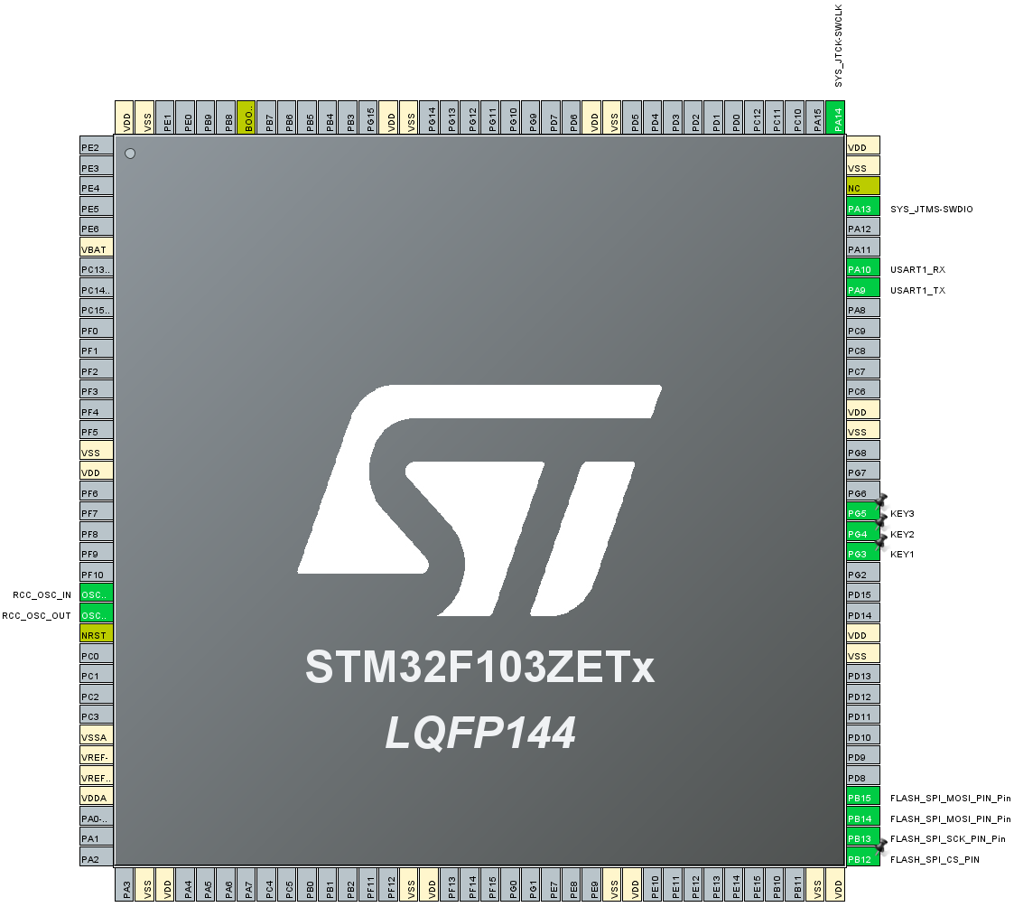
- Configure the specified pin function
You can directly select the corresponding pin number in the pin view, and the corresponding option will appear when the mouse is left clicked
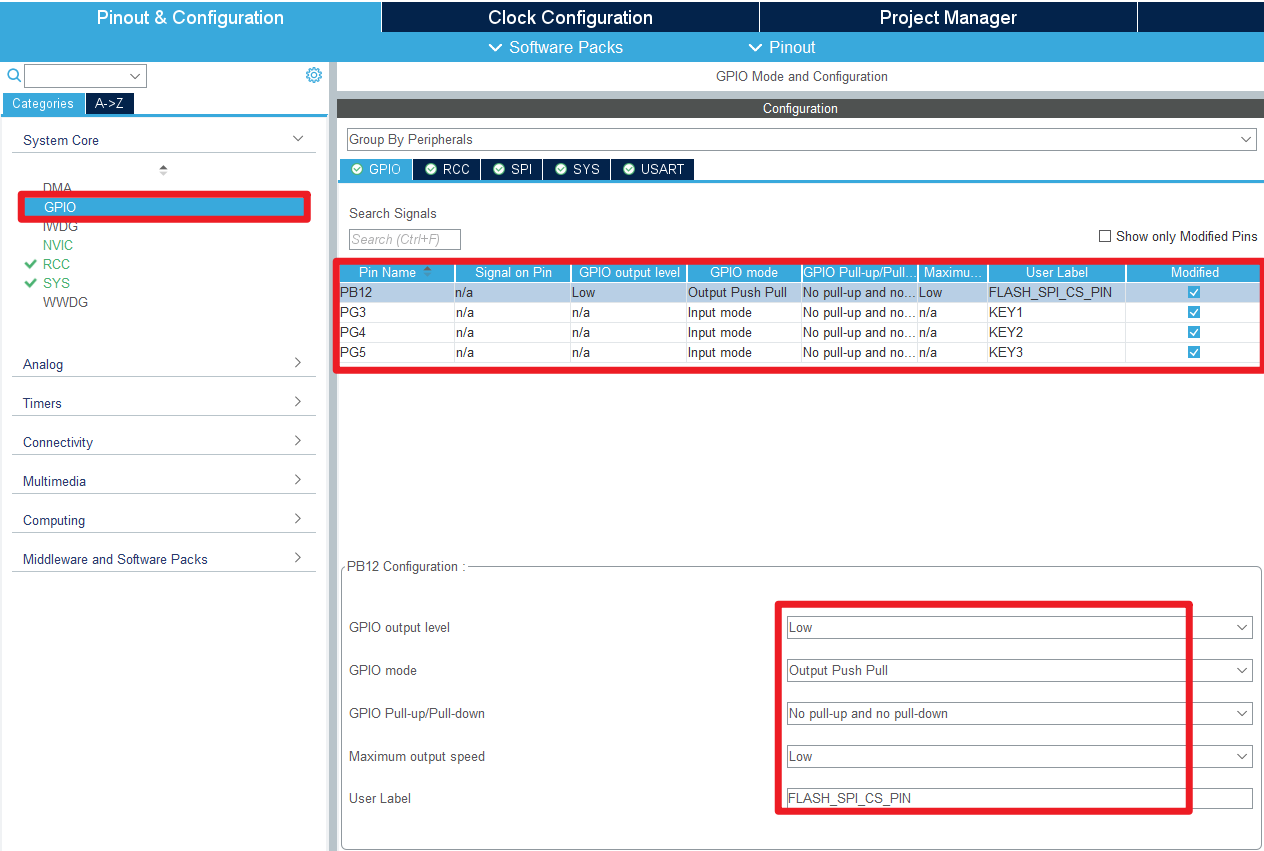
- GPIO
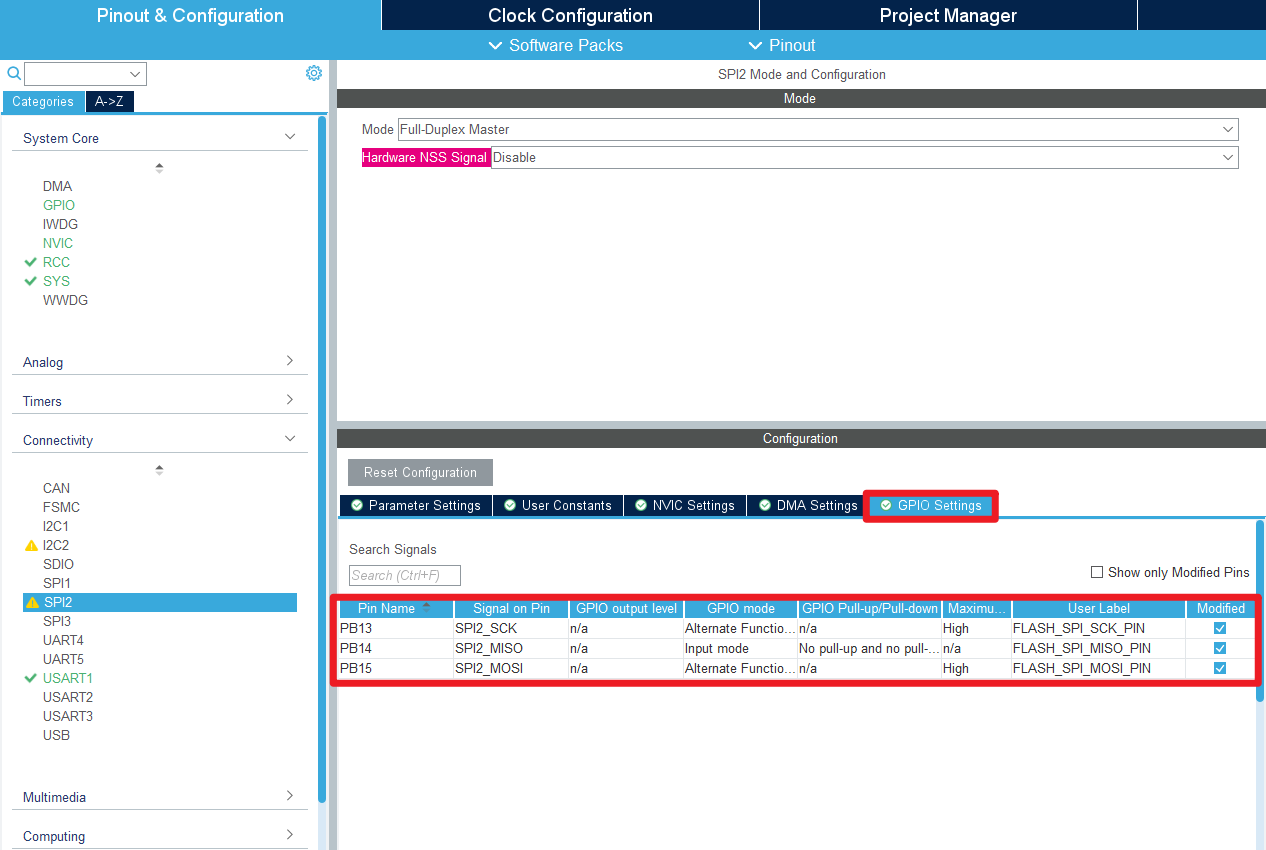
- SPI


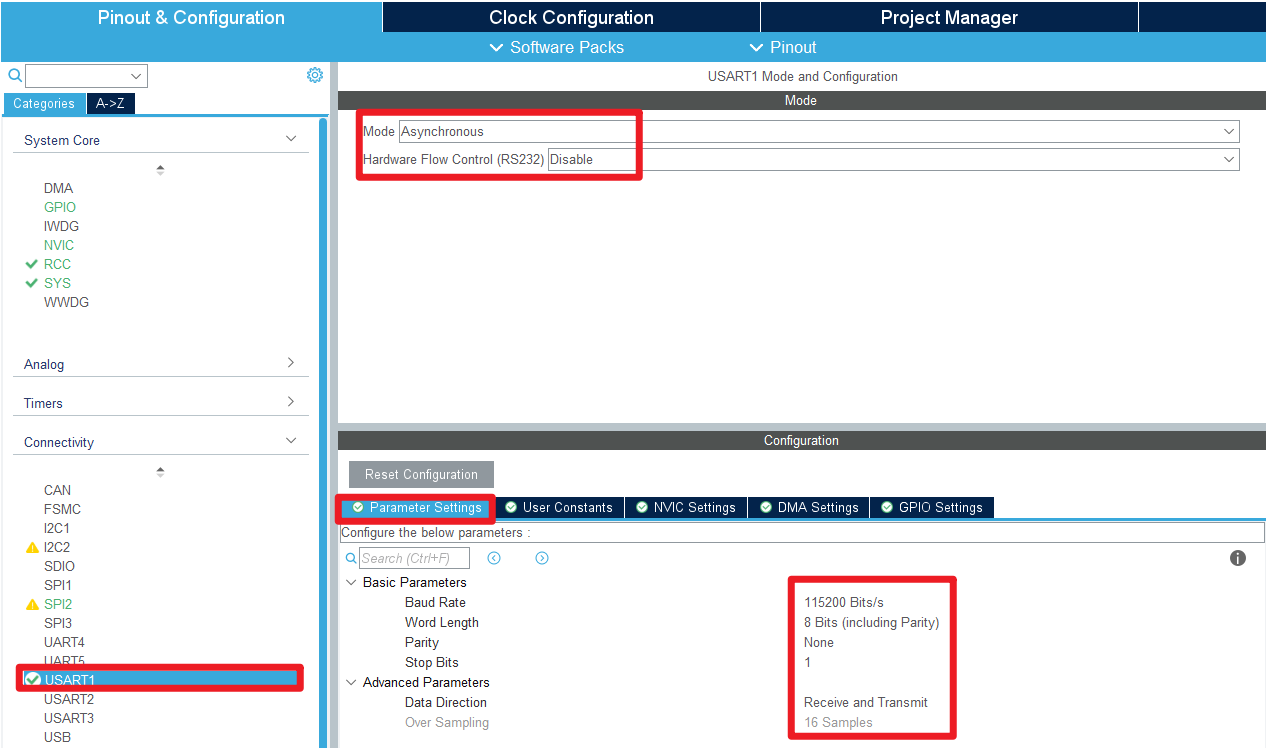
- USART

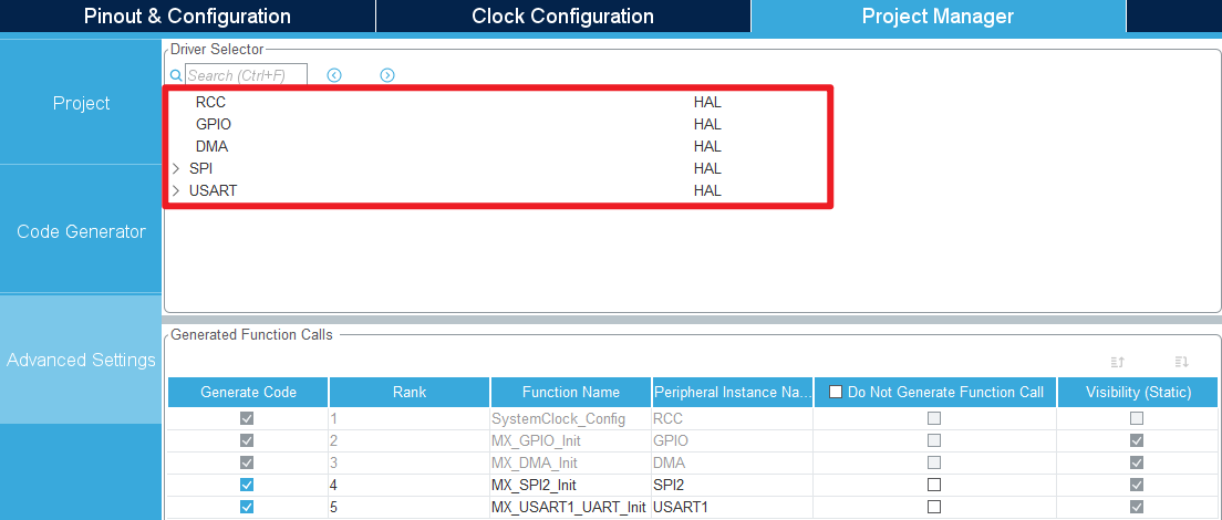
- Advanced Settings
- Generating code

4、Main function
This section mainly introduces the functional code written by users. Detailed code can be opened by yourself in the project file we provide, and enter the Bsp folder to view the source code. .
4.1、User function
[Chapter 3: Off-chip Flash] Functions introduced are no longer covered
function:SPI_Read_Write_Byte
| Function prototypes | uint8_t SPI_Read_Write_Byte(uint8_t BYTE) |
|---|---|
| Functional Description | 1 byte of data is sent via SPI |
| Input parameters | BYTE:data |
| Return value | 0 |
| Tips | defined DMA_SPI_USE macros used to switch the DMA data transmission or |
function:SPI_Write_DMA
| Function prototypes | uint16_t SPI_Write_DMA(uint8_t *pTxData, uint16_t Size) |
|---|---|
| Functional Description | Data is sent via DMA |
| Input parameters1 | pTxData:Data head address |
| Input parameters2 | Size:Number of bytes of data |
| Return value | HAL status value:HAL_OK、HAL_ERROR、HAL_BUSY、HAL_TIMEOUT(0-3) |
4.2、HAL library function parsing
The HAL library functions that were covered in the previous tutorial will not be covered
xxxxxxxxxxIf you want to find the HAL library and LL library function analysis involved in the entire tutorial, you can view the documents in the folder [8. STM32 Manual: STM32F1_HAL Library and LL Library_User Manual]
function:HAL_DMA_Init
| Function prototypes | HAL_StatusTypeDef HAL_DMA_Init(DMA_HandleTypeDef *hdma) |
|---|---|
| Functional Description | Initialize the DMA controller |
| Input parameters | hdma:DMA handle address |
| Return value | HAL status value:HAL_OK、HAL_ERROR、HAL_BUSY、HAL_TIMEOUT |
function:HAL_SPI_TransmitReceive_DMA
| Function prototypes | HAL_StatusTypeDef HAL_SPI_TransmitReceive_DMA (SPI_HandleTypeDef *hspi, uint8_t *pTxData, uint8_t *pRxData,uint16_t Size) |
|---|---|
| Functional Description | Sending and receiving SPI data via DMA mode |
| Input parameters1 | hspi:SPI handle address |
| Input parameters2 | pTxData:The first address to send data to |
| Input parameters3 | pRxData:The first address to receive data |
| Input parameters4 | Size:The number of bytes of data sent and received |
| Return value | HAL status value:HAL_OK、HAL_ERROR、HAL_BUSY、HAL_TIMEOUT |
function:HAL_SPI_Transmit_DMA
| Function prototypes | HAL_StatusTypeDef HAL_SPI_Transmit_DMA (SPI_HandleTypeDef *hspi, uint8_t *pData, uint16_t Size) |
|---|---|
| Functional Description | SPI send function that transfers data using DMA |
| Input parameters1 | hspi:SPI handle address |
| Input parameters2 | pData:The first address of the data |
| Input parameters3 | Size:Number of bytes of data |
| Return value | HAL status value:HAL_OK、HAL_ERROR、HAL_BUSY、HAL_TIMEOUT |
5、Experimental phenomenon
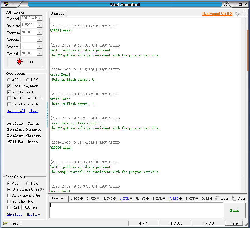
After downloading the program successfully, press the RESET button of the development board to open the serial debugging assistant to observe the phenomenon
xxxxxxxxxxFor program download, please refer to [2. Development environment construction and use: program download and simulation]
phenomenon:
Press RESET button: the serial debugging assistant will print the detection status of the external Flash chip;
Press KEY1: The serial debugging assistant will add 1 to the count value and write the value to the external Flash chip;
Press KEY2: The serial debugging assistant will output the numerical value stored in the specified sector of the external Flash chip;
Press KEY3: The serial debugging assistant will erase the specified sector data.