Welcome to STM32-BoardCar repository
5. Infrared sensor
Infrared sensor
Infrared sensor1、software-hardware2、Brief principle2.1、Hardware schematic diagram2.2、Physical connection diagram2.3、Principle of control3、Engineering configuration3.1、Notes3.2、Pin configuration4、Main FunctionUser function5、Experimental phenomenon
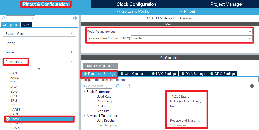
This tutorial demonstrates how to print the converted values of two infrared obstacle avoidance module ADMs via serial port (USART1) .
1、software-hardware
STM32F103CubeIDE
STM32 robot expansion board
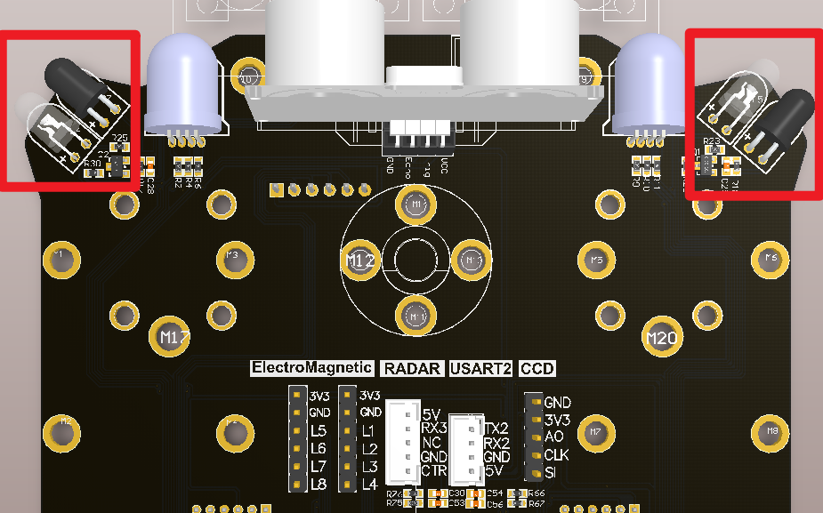
Two infrared obstacle avoidance modules are integrated on the development board
Type-C cable or ST-Link
Download or simulate the program of the development board
2、Brief principle
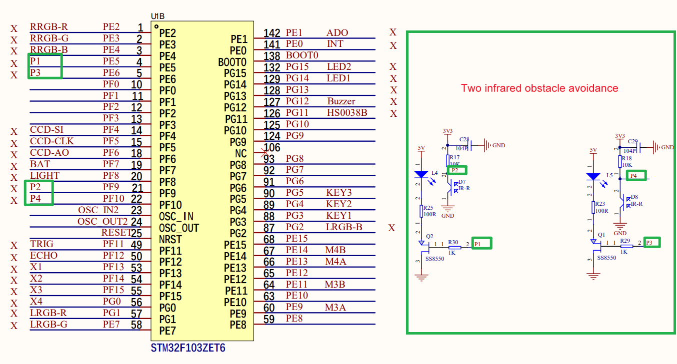
2.1、Hardware schematic diagram
2.2、Physical connection diagram
2.3、Principle of control
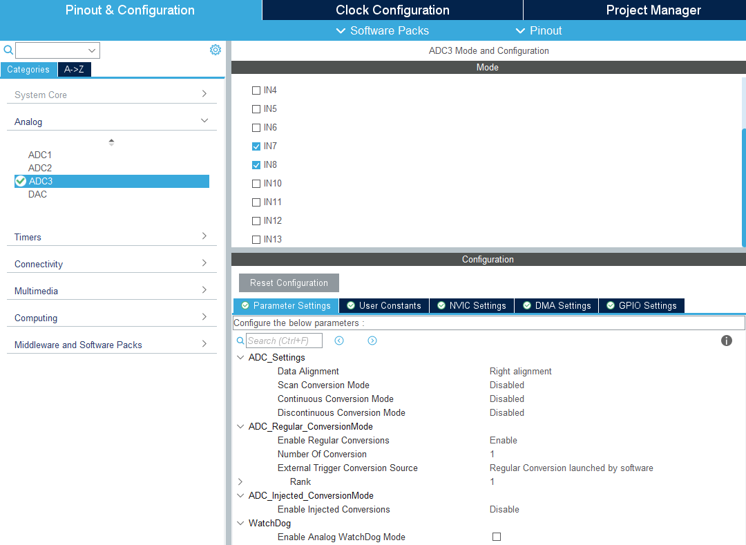
The analog voltage output of infrared obstacle avoidance module can be converted to digital value by two ADC conversion. The range is 0 to 2^12-1 (that is, 0 to 4095).
| Infrared obstacle avoidance (development board integration) | Corresponding pin |
|---|---|
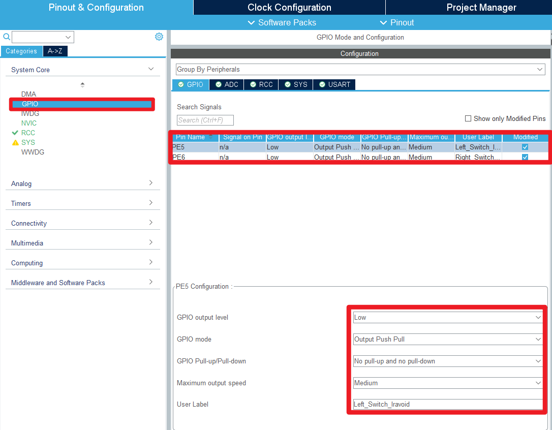
| P1 | PE5(Control the left obstacle avoidance module switch) |
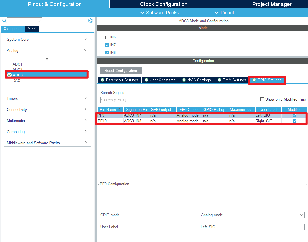
| P2 | PF9(ADC3_IN7) |
| P3 | PE6(Control the switch of the right obstacle avoidance module) |
| P4 | PF10(ADC3_IN7) |
3、Engineering configuration
Project Configuration: Prompts for configuration options in the STM32CubeIDE project configuration process
3.1、Notes
Omitted project configuration: New project, chip selection, project configuration, SYS for pin configuration, RCC configuration, clock configuration, and project configuration content
The project configuration part, which is not omitted, is the key point to configure in this tutorial.
Please refer to [2, development environment construction and use: STM32CubeIDE installation - Use] to understand how to configure the omitted part of the project
3.2、Pin configuration
- GPIO
- USART
- ADC
- Advanced Settings
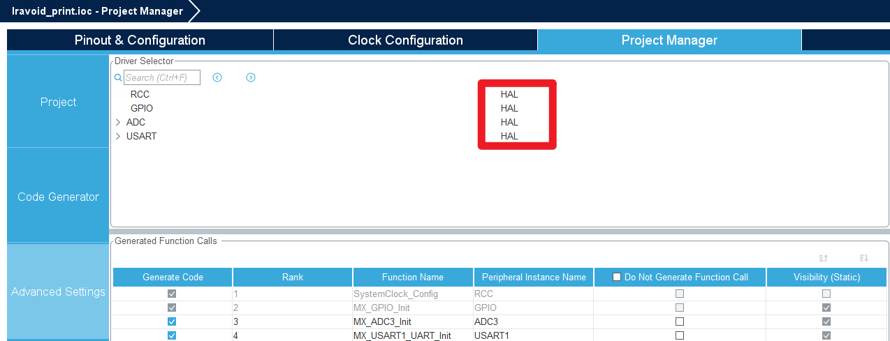
- Generating code

4、Main Function
This paper mainly introduces the functional code written by users. ** Detailed code can be opened by yourself in the project file we provide, and enter the Bsp folder to view the source code. **.
User function
Many of the common HAL library functions were covered in Chapter 3, but they will not be covered here.
函数:Adc_Get_Iravoid
| Function prototypes | uint16_t Adc_Get_Iravoid(uint32_t ch) |
|---|---|
| Functional Description | The converted values of the infrared sensor ADC are collected |
| Input parameters | ch:channel |
| Return value | ADC converted value |
函数:Get_Iravoid_Data
| Function prototypes | void Get_Iravoid_Data(uint16_t *left_data,uint16_t *right_data) |
|---|---|
| Functional Description | Print the converted values of the two infrared sensor ADCs |
| Input parameters1 | left_data:Infrared sensor values on the left |
| Input parameters2 | right_data:Infrared sensor values on the right |
| Return value | None |
5、Experimental phenomenon
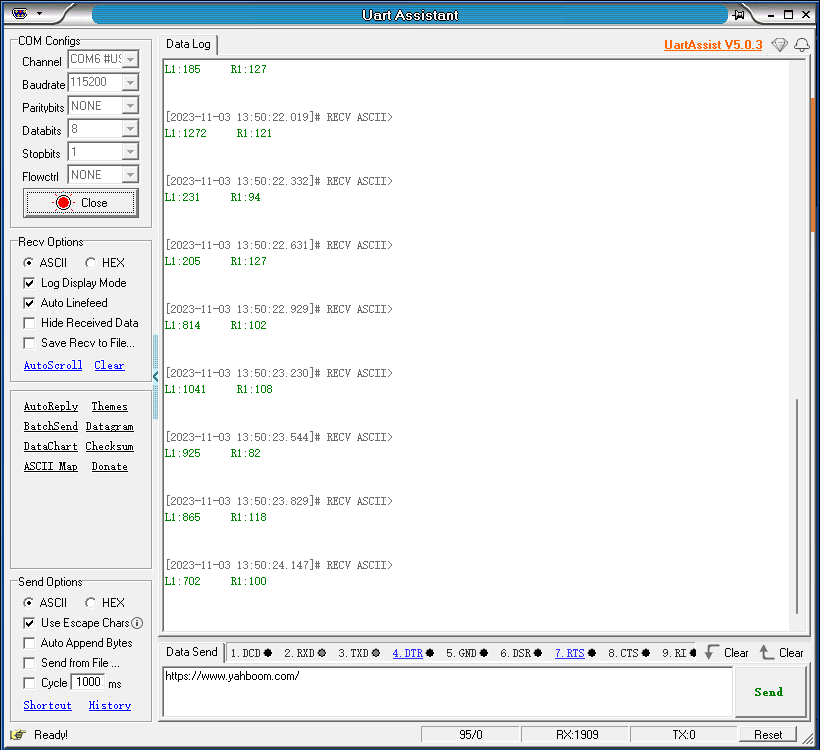
After downloading the program successfully, press the RESET button of the development board to observe the phenomenon of serial debugging assistant
xxxxxxxxxxProgram download can refer to [2, development environment construction and use: program download and simulation]
phenomenon:
The serial port continuously prints the converted values of the two infrared sensor ADCs with a time interval of 0.3 seconds.